The Future Potential of 5G with Millimeter Wave Antennas
A millimeter wave link is not an upgraded microwave link. It is a different engineering problem that happens to carry data, and the difference shows up in the aperture, the pointing tolerance and the number of sites somebody has to build and power. We make RF hardware from UHF through the microwave bands up to 13.4 GHz, which makes us the supplier on the lower side of most of these arguments. That vantage point is still worth having, because the parts that decide whether a millimeter wave layer ever pays for itself are mechanical long before they are commercial.

Why the shorter wavelength is not simply faster
Spectrum is the honest case for the band. Above 24 GHz a single licensed block can be wider than everything the crowded lower ranges offer in total, and wide blocks buy capacity per site without buying more antennas or more radio chains. The bill arrives as propagation. Free-space loss climbs with frequency while diffraction around obstacles falls away, so a millimeter wave cell behaves like a beam with a shadow behind it rather than a pool of coverage. Walls, tree canopies and even wet foliage stop being background assumptions and become planning inputs. None of that argues against the band; it argues for modelling it with obstruction data in hand rather than with a coverage radius copied from a lower frequency.
The aperture argument runs the other way
Shorter wavelengths also shrink the aperture needed for a given gain, and that is the part vendors quote first. Our top microwave panel covers 12.7 to 13.4 GHz through a single WR62 waveguide flange and holds 28 to 30 dBi across a face measuring 340 by 340 mm and only 30 mm deep, at 2.5 kg. Move the same gain requirement higher in frequency and that face contracts again. The trap is that a narrow beam must be aimed: a smaller antenna is not a smaller installation, because the mounting structure, the wind load and the rigging labour all remain while the angular tolerance tightens. A pattern that is three degrees wide leaves very little room for a mast that flexes.
Density, not speed, is the real cost
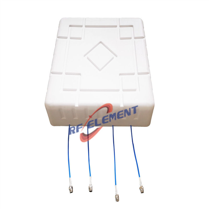
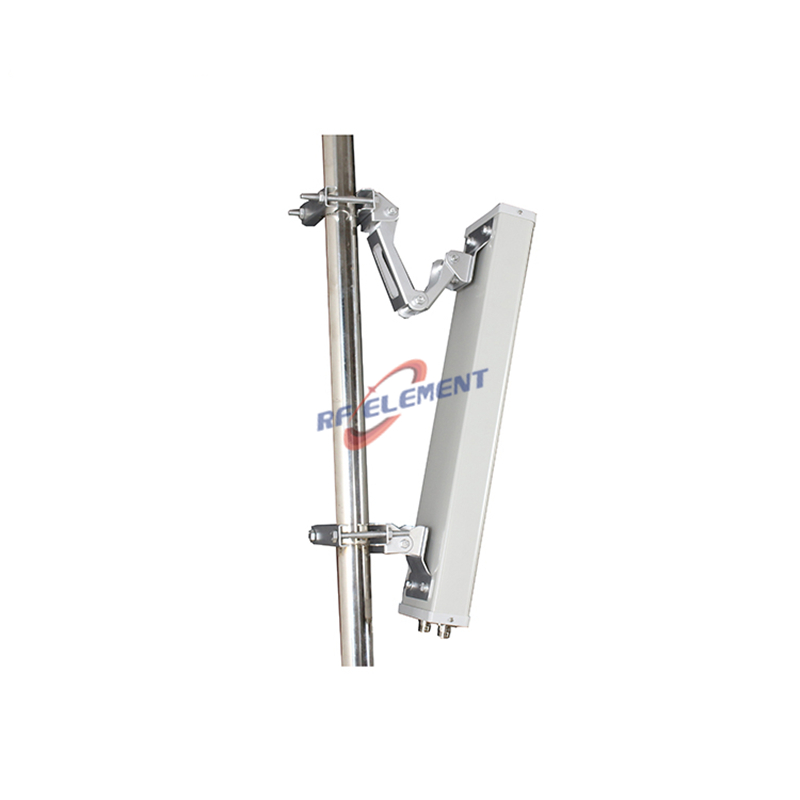
The capacity is genuine, and so is the site count. A millimeter wave layer is a small cell layer by construction, which shifts spending from spectrum to civil works, backhaul and power. That is where the wideband hardware we build does most of its work, and it is where the physics of the lower bands still wins. Take the street-level small cell panel we build for lamp posts and bus shelters: 617 to 4200 MHz, 7.5 dBi over an 80 degree horizontal and 45 degree vertical pattern, four ports 50 W each, path-to-path isolation of at least 15 dB, and third-order PIM of -153 dBc so it can share a pole with other radios. Two of those on one post will serve a residential street with no new trenching, which is often the whole business case. A 5G MIMO panel antenna in the same family does the indoor half of the job from a body measuring 360 mm along the pole, 155 mm across and 65 mm deep at 1.1 kg, with 6 dBi and 20 dB of port isolation.
Fixed wireless is where the band already works
There is one deployment shape where millimeter wave quietly performs, and it is the one where nobody moves. A fixed wireless access link between a rooftop and a hub has a terminal that can be aimed once and left alone, which removes the two costs that break the mobile case: handover and continuous re-aiming. The same logic applies to a private campus or a warehouse, where the geometry is surveyed and the owners control both ends of the path. In those designs the argument is no longer coverage radius, it is whether the required gain can be delivered in a package the building will accept. If the answer is a 30 cm panel on a parapet rather than a metre-wide dish, the higher band is doing real work. Where the answer is a 600 mm or 900 mm reflector, the lower bands still deliver the same link at a fraction of the installation cost.
Where millimeter wave is the wrong choice
The band is wrong whenever the geometry cannot be changed. A street canyon with no dependable line to the far end, a suburban run where a mast has to reach past mature trees, a terminal that moves at speed and hands over between cells, or a site where the mounting point sags in summer heat will each cost more in civil works than the extra spectrum is worth. It is also the wrong call when density cannot be funded: if the business case only closes at a quarter of the sites the coverage plan needs, the layer gets built and then quietly under-filled. And it is wrong when the far end runs on a tight solar budget, because a three degree beam needs re-aiming after wind events that a 65 degree sector would never notice. Rain belongs on the same list. A short shower that costs a lower-band link a fraction of a decibel can cost a high-band path several, which either eats the fade margin or forces a shorter hop than the terrain suggested.
What carries the traffic instead
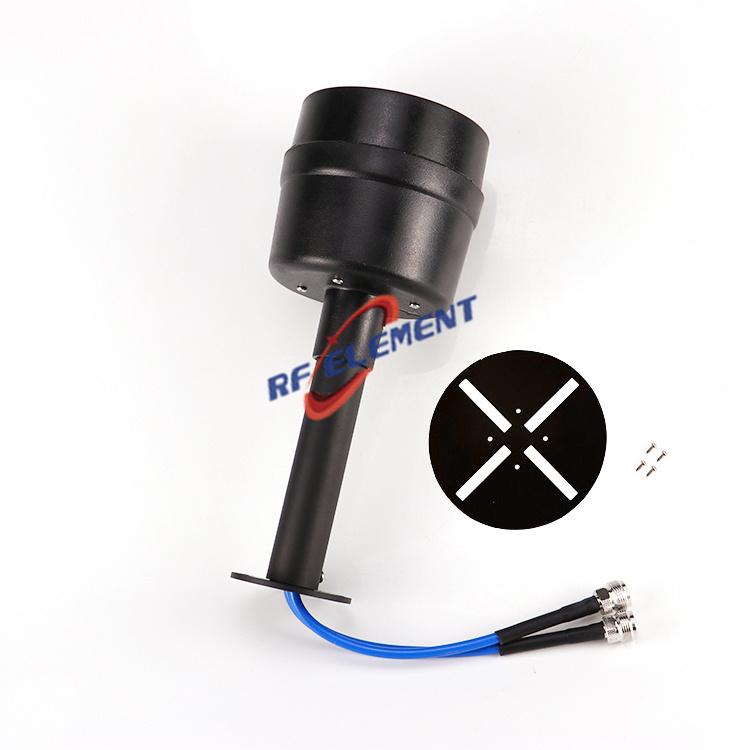
For a fixed hop between two points that never move, a dish at microwave frequencies is the cheaper answer, and it is usually available sooner. Our 4.9 to 6 GHz dual-polarized dishes deliver 31 dBi from a 900 mm reflector, and 28 dBi from a 600 mm dish that weighs 7 kg. Compare that with the 900 mm microwave dish or the smaller 600 mm microwave dish directly and the trade is visible: the large one adds cross-polar isolation of 30 dB or better and front-to-back of 35 dB, which is what stops a crowded mast from turning into an interference study. Both accept 100 W through two feeds and hold beams only 4 to 5 degrees wide. If an existing parabolic is already on the tower, a feedhorn for parabolic dishes covering 1700 to 4200 MHz returns 25 dBi on the larger mesh reflector and 23 dBi on the smaller solid one from a horn of 0.6 kg.
Where the aperture has to shrink rather than grow
The last leg of a link often needs gain in a volume nobody wants to give up, and that is where a compact 13 GHz panel for the last leg earns its place: 12.7 to 13.4 GHz, up to 1000 W, VSWR within 1.8 into 50 ohm, IP65 behind a white ABS radome, on a face a little over 30 cm square. That is the ceiling of what we manufacture, and it is also where most millimeter wave discussions land in practice. A 7 GHz microwave MIMO dish reaching 32 dBi with beamwidth below 3 degrees in both planes will close a hop that would otherwise demand a far more expensive band, and it will do it with hardware that ships on a normal lead time. Band choice and aperture choice are the same decision seen from two directions, and a supplier who makes both ends of that range can say so without steering the answer.
What to send us
Give us the licensed band, the hop distance, the obstruction profile and the mast height you can actually obtain, and say plainly whether the far end moves. Send those four items to sales@rfelement.com; anything we send back will name a band and an aperture, not a technology. If the high-band layer is already committed and you need the feeder and dish hardware underneath it, put that in the same message, because the two decisions constrain each other more than most project plans admit.
TAG:The Future Potential of 5G with Millimeter Wave Antennas https://www.rfelement.com