4G LTE Ceiling Antenna Solution for Metro system
A metro platform asks a different question of an antenna than an open concourse does. Riders stand directly beneath the ceiling, the ceiling is often the only surface left available, and the service that must not fail is still a voice call handing over between two stations. Everything we specify for tunnel and platform coverage follows from those three facts.
The ceiling is the only place with a view of the riders
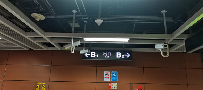
A head-end can be flawless and still deliver nothing if the radiating element looks at the wrong volume. In a tunnel cross-section the practical RF real estate is the ceiling plane. Side walls carry signage, cable trays and finishes; the platform edge belongs to the train and to the platform screen doors; the track bed belongs to nobody. A ceiling disc places the pattern over the walking level, keeps hardware out of reach, and leaves the finishes undisturbed. That is the entire case for the format, and it is why metro work rarely begins from a wall panel.
Three discs, one electrical span
The three ceiling antennas below share the same span and the same interface discipline: 698-3800 MHz, a 4.3-10 female port, VSWR held at or below 1.8, a 50 W rating, and third-order passive intermodulation of -150 dBc under 2×43 dBm tones. What changes between them is the shape of the field and the depth of the housing.
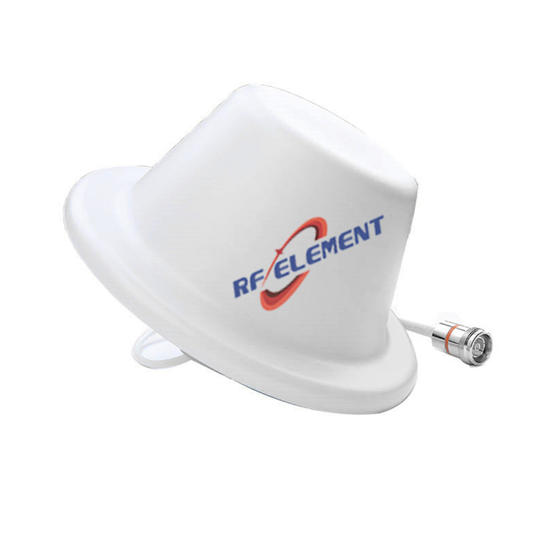
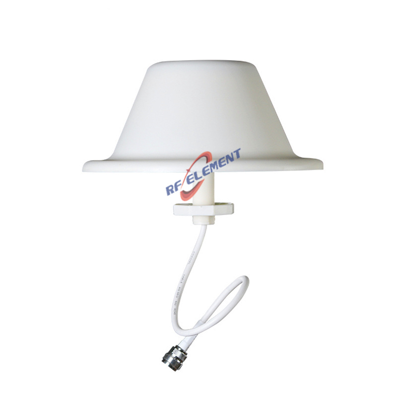
The 5G cellular ceiling disc is the deepest of the three at φ186 × 85 mm and the most contained in the vertical plane: 1.5 dBi over a 360° horizontal by 60±10° vertical pattern, which drops energy onto the walking level instead of into the tunnel crown. Where the void above the ceiling cannot spare 85 mm — a listed station, a retrofit over a suspended grid — the low profile ceiling disc performs the same duty from φ186 × 15 mm, at 2.5 dBi with the vertical coverage widened to 90±10°, so one point reaches further along the platform. Each tips the scale at 0.3 kg and ships with the fittings for a ceiling fixing.
When the radio carries two streams, the same tile becomes a two-path point. The MIMO low profile ceiling antenna keeps horizontal plus linear polarization on one φ280 × 15 mm, 0.5 kg body, again 360° by 90±10° at 2.5 dBi. Two paths from a single ceiling position is what separates a 2×2 radio running at its rated rate from the same radio running at half of it.
The band plan the tunnel will grow into
Tunnel infrastructure is built once and refreshed on a much slower rhythm than the radio. One span of 698-3800 MHz lets the operator re-farm 700, 800, 900, 1800, 2100 and 2600 MHz LTE carriers and then light sub-6 GHz 5G on the same ceiling hardware, without a second visit above the ceiling. A band-specific disc is cheaper on the purchase order and considerably more expensive by the second generation of service. That trade is the reason the wide span appears on all three parts above.
Passive intermodulation is not a formality underground
A tunnel DAS is a chain of collinear junctions: jumpers at the head-end, splitters, couplers, and the antenna port itself, every one of them a place where two carriers can mix. Intermodulation that would pass unnoticed on a rooftop becomes a raised noise floor across the whole run once the chain is long and the traffic dense. The ceiling line is rated -150 dBc under 2×43 dBm. The discipline continues down the line too: the 4G LTE booster disc covers 698-2700 MHz at 3 dBi with VSWR inside 1.5 on a lone N-type female connector, the housing measuring φ185 × 90 mm at 0.4 kg; and the low PIM 5G wall panel tightens the figure to -153 dBc, 6 dBi across 90±15° horizontal by 85° vertical, with a front-to-back figure of at least 10 dB inside a 165 × 155 × 45 mm body at 0.4 kg; it is the part for a platform end wall where coverage has to be aimed rather than spread.
What a tunnel does to the hardware
Heat, humidity and vibration are the three conditions a metro installation never escapes. A disc specified for a -55 to +60 °C window handles a tunnel that runs warm with braking trains in July and cold at a surface portal in January, and the ABS radome does not care which end of that range it is sitting at. Humidity is the second condition: a tunnel keeps its own climate, and a sealed radome with an ABS shell is the answer to condensation that never fully dries. Vibration is the quieter problem: a ceiling fixing above a running line sees continuous low-level movement, which is why these discs ship with fasteners sized for a structural ceiling rather than a decorative tile, and why the ceiling build-up is requested before any mounting drawing is signed off. None of it is exotic hardware; all of it separates a coverage plan from a coverage plan that is still true in year three.
Handover at the platform edge
Coverage that stops at the platform is coverage that drops a call the moment the doors close. The pattern and the spacing between discs set the overlap, and overlap is what a handover consumes: there has to be usable signal on both sides of the boundary for the network to complete the transfer before the old cell fades. Along a straight platform the low profile disc's 90±10° vertical figure gives the longest reach per point; in a curved or stepped station the 60±10° disc keeps more of the energy inside the platform envelope. Place the two together and the boundary lands where you planned it rather than wherever the geometry happened to put it.
Where the metro spec goes wrong
Three mistakes appear in almost every tunnel brief we are asked to price. The first is choosing a high-gain panel to save antenna count: gain bought on the horizontal plane floods the track bed and the neighbouring platform, and the remedy is more ceiling points rather than more dBi. The second is specifying for today's band plan only, which guarantees a second installation above a finished ceiling later. The third is treating PIM as a head-end specification while leaving the radiating chain to whatever the installer has on the van; on a long collinear run the antenna port counts for as much as the amplifier.
Environment, fixing, and what we need from you
Every disc in the line carries an ABS radome and works between -55 and +60 °C, and that window covers a tunnel running warm with train traffic in summer and cold at the portals in winter. Fixing is a ceiling surface plus a cable run; the hardware itself raises no structural question.
Send us the tunnel or platform cross-section, the band plan you intend to run in five years as well as today, the ceiling void depth, and the radio's port count. Our reply names the disc, sends the full specification table, works through the mounting detail with you, and flags any overlap or PIM risk visible in the layout. Evaluation discs ship roughly five working days from drawing sign-off, volume scheduling follows confirmed quantities, and the MOQ is sized so a single-station pilot can be built before any line-wide commitment. Message us at sales@rfelement.com — the pattern you sign off on is the pattern the tunnel actually receives.
TAG:4G LTE Ceiling Antenna Solution for Metro system https://www.rfelement.com