Fiberglass Radome for Antennas: Material, Process, Selection
A radome has one job in the electrical sense and several in the mechanical sense, and the two sets of requirements pull against each other. Electrically the shell should not exist: it should pass the wave through without bending it, absorbing it or detuning the radiator underneath. Mechanically it has to keep rain out of the feed, hold ultraviolet light off the copper, survive ice and wind load, and stay dimensionally stable across a range a mast in direct sun and a winter night will both test. A fiberglass radome is the usual answer when that balance has to hold outdoors for a decade.
The electrical job is to be almost invisible
A shell sitting in the near field of a radiator is not a passive object. Its dielectric constant and its wall thickness together shift the resonant frequency of whatever sits inside, and the shift shows up as return loss rather than as a hole in the pattern. Two consequences follow. First, the wall has to be thin and consistent, because a shell whose thickness varies across its curve behaves like a different material at every point. Second, the choice is frequency-dependent: a wall that is electrically negligible at 900 MHz can cost real loss at 5.8 GHz, since the same physical thickness represents a larger fraction of a wavelength as frequency climbs. That is why a radome is specified alongside the antenna rather than picked from a catalogue afterwards.
Four shell materials, and what each one costs you
The catalogue shows the trade-offs, because we build in all four.
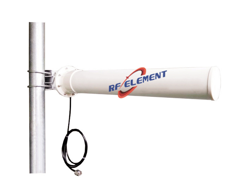
Fiberglass. Our 3.4-3.8 GHz omni hangs its vertical radiator in a glass tube 42 mm across and 630 mm long, delivering 11 dBi with VSWR inside 1.8 and a 360 degree azimuth pattern just 8 degrees thick. The LoRa omni uses the same approach in a 22 mm by 600 mm tube, 5 dBi and a 35 degree vertical beam. Glass-reinforced shells buy stiffness at low weight and hold their colour and strength under UV, which is why they dominate the long thin outdoor omnis.
ABS. Our 2.4 GHz Yagi puts a 15 dBi beam, 33 degrees horizontal by 30 vertical, into a 75 mm by 505 mm ABS shell at 1.5 kg with VSWR at or under 1.5. ABS moulds cleanly and cheaply and takes a UV stabiliser well, which makes it a sensible shell for a product on a pole under a lease that lasts a few years rather than a decade.
PVC. The 2.4/5.8 GHz sector in our range uses a vinyl body just under a metre long, and the 90 degree 5 GHz sector uses the same material in a body barely half that. Vinyl brings good dielectric behaviour and a well-behaved moulding profile, at the cost of mass.
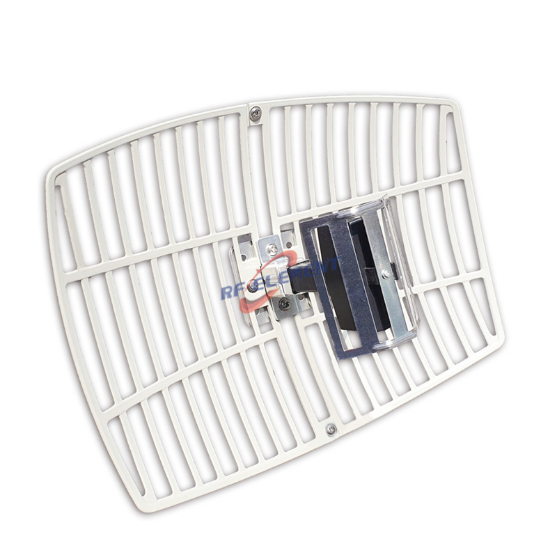
Aluminium. This is not a radome in the electrical sense at all. On the 300 by 400 mm parabolic grid the metal is the reflector and the aperture is left open on purpose, because an open frame carries about half the wind load that a closed reflector of equal gain presents. Where the metal forms a closed cover instead, it shields the antenna — a legitimate choice for a mechanical guard and a fatal one for a radiating surface.
The comparison worth carrying into a specification meeting is that these are not quality tiers. Each is the right answer to a different combination of frequency, wall thickness, service life and wind exposure.
The 15 percent glass problem
A client in Mexico approached us for a radome over a radar antenna installed outdoors, and the requirement was specific: a plastic fiberglass shell with glass fibre reinforcement exceeding 15 percent. That figure is where the process stops being simple.
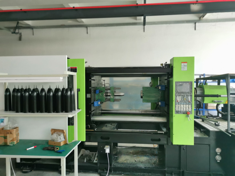
Glass fibre raises the viscosity of the compound and cuts its flowability. In an injection moulding tool that means the melt does not fill the cavity evenly, pressure during the shot becomes hard to control, and the places where filling is worst are exactly the places a radome cannot afford a defect: the thin curved wall and the sealing land at the base. Push the content up for stiffness and it is paid for in fill, finish and reject rate.
How a heavily reinforced shell actually gets moulded
Three things had to change together to make that 15 percent requirement producible.
The cycle. A process tuned for unfilled plastic will not fill a high-glass cavity consistently, so the shot had to be built around the higher viscosity rather than adjusted to it after the fact.
The tool. Mould design carries most of the burden. Runner and gate geometry, venting and cooling all had to be reworked so the melt reached the far wall of the shell at a pressure and temperature it could still form with, which is what keeps wall thickness even across the curve.
The glass-to-resin interface. Surface treatment agents decide how well the fibre bonds to the resin matrix. Get that bond wrong and the reinforcement stops reinforcing: the shell can pass a visual inspection and still lose strength and weather resistance in service.
The development sequence was conventional in shape and demanding in detail. Material selection first, balancing strength against workability rather than maximising either. Moulding process optimisation next, run specifically for the high-fill compound and verified on structural integrity and weather resistance rather than on cycle time. Quality assurance last, with checks written against the client's specification instead of a generic cosmetic standard. The finished shell fitted the radar antenna as drawn and has since done its job in outdoor service.
Where a reinforced shell is the wrong answer
Frequency decides more of this than most specifications admit. At 5.8 GHz a wall that would be electrically transparent at 900 MHz starts to look thick, and a heavily filled compound with a higher dielectric constant makes that worse rather than better. If the antenna is a 5 GHz sector or a 5.8 GHz bridge, the priority is a thin, uniform, low-loss wall, and the reinforcement content should be set by the mechanical load rather than by habit.
The second case is cost with no exposure. An antenna that lives in a sealed equipment room or a controlled enclosure needs no UV resistance, no water shedding and no ice rating, and the premium for a glass-reinforced shell buys nothing that any observer will ever see. Where the same job has to be done outdoors at a low band, a 900 MHz Yagi gets its weather protection from an aluminium boom and a sealed cover rather than from a reinforced shell — a reminder that the material follows the application, not the other way round.
Briefing a custom radome
Two documents decide whether a quotation comes back accurate. The first is the mechanical envelope: the antenna's outer dimensions, the sealing surface it has to mate with, the mounting points, and the wind and ice load the site imposes. The second is the electrical requirement: the band, the wall thickness the design allows, and the return loss the antenna has to hold with the shell in place.
Send those two and the reply will carry the material recommendation, the wall construction, a drawing of the shell and its sealing detail, plus a note on the dielectric or dimensional risk your design raises. We handle radome development, the injection moulding and antenna array production under one roof, which is why a shell and the antenna it covers can be tuned against each other instead of being matched afterwards. Sample shells come off the line in under a week from drawing release, series dates are tied to the confirmed quantity, and the opening order is deliberately small so one prototype installation can be measured before a programme is awarded. The envelope and the band are all the brief needs: sales@rfelement.com. The return loss your antenna holds with the shell fitted is the figure we will be judged on.
TAG:Fiberglass Radome for Antennas: Material, Process, Selection https://www.rfelement.com