RF element, The Dual Band and Multiple Antennas WiFi Hotspot Solution
A WiFi hotspot is a shape problem before it is a parts list. The site gives you one mounting point and a scatter of client devices across an area that is rarely symmetrical; the job is to arrange coverage so the busy arc gets capacity and the quiet arc merely gets signal. That is the reasoning behind every multi-antenna hotspot we quote.
Two bands, two different jobs
The 2.4 GHz band travels further and passes walls and foliage more easily; the 5 GHz band carries more throughput per hertz but behaves almost like light. A hotspot that treats the two as interchangeable ends up either thin at the edges or congested at the centre. The layout that resolves it puts a wide 2.4 GHz omni at the mast to serve the whole area, then adds 5 GHz sector antennas aimed at the arcs where users actually gather — the entrance, the queue, the seating block. Both bands then have a job, and neither is asked to do the other's.
The three parts that make the pattern
The 2.4 GHz MIMO omni is the blanket: 2400-2500 MHz on horizontal plus vertical polarization, 13 dBi, a 360° horizontal by 8° vertical pattern, VSWR held within 1.5, a 50 W rating, two N-type female connectors, in a Φ75 × 1150 mm, 3.2 kg pole-mounted tube with a white ABS radome. Its vertical figure is what keeps the ring flat and stops the mast lighting the far horizon as well as the car park.
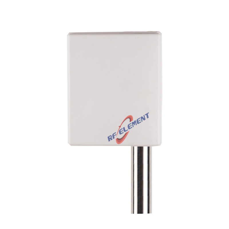
The dual band sector plate is the capacity tool: 2400 to 2500 MHz, and 5720 to 5850 MHz, on horizontal plus vertical polarization, 14 to 16 dBi with horizontal beamwidths of 65° and 90° and vertical beamwidths of 15° and 7° across the two bands. It carries a quartet of N-type female connectors for two bands of 2×2 MIMO, handles 100 W, holds VSWR within 2.0, and closes in a PVC radome measuring 980 by 128 by 58 mm at 3.5 kg on a pole. Four connectors on one plate is what lets a single mast run both bands without a second mounting bracket.
Between them sits the dual band 3×3 MIMO omni: 2400 to 2500 MHz and 5150 to 5850 MHz, vertical polarization, 7.5 dBi with 28° and 25° vertical beamwidths, six SMA female connectors split three per band, 50 W, VSWR within 2.0, in a Φ132 × 280 mm, 1.0 kg ABS tube. It is the choice for a mast where both bands need an omni footprint and the sector arcs are too small to justify a plate of their own.
MIMO needs paths, not promises
Every part above is specified by connector count because MIMO throughput is bought with independent paths. A 2×2 client on 2.4 GHz needs two feeds into the same coverage volume; a 3×3 client needs three. When the antenna offers one port per band, the radio and the client negotiate a rate the antenna cannot carry and the shortfall is usually blamed on the access point. Counting ports before counting dBi is the habit that prevents it. For a mast that must also carry a private-network or backhaul link, the n78 fiberglass omni spans 3400-3800 MHz at 11 dBi on a Φ42 × 630 mm tube, and the 13 GHz microwave panel takes the point-to-point hop where the unlicensed WiFi spectrum is too crowded to trust.
Aiming the sectors
A sector plate is a promise about azimuth, and azimuth is set by the pole rather than by the antenna. Three plates on one mast should be spaced around it so their main lobes tile the busy arcs with a controlled overlap — enough to pass a client between sectors without a dip, not so much that two sectors fight over the same users. The 5 GHz vertical beamwidth is the tool here: at 7° the main lobe is a flat sheet, so a small change in downtilt moves the coverage edge a long way along the ground. We ask for pole height and the arc plan before naming a downtilt, because the same plate on a 6 m mast and on a 12 m mast draws two different coverage maps.
Cabling, ports and the run to the switch
Connector count is the easy half of the interface; the cable is the other. Six SMA female connectors on the dual band omni mean six short pigtails to the radio, and on a mast those runs want to be dressed and weatherproofed rather than left to hang. The four N-type connectors on the sector plate suit a longer, higher-power run from a cabinet, and the 100 W rating exists so the antenna is never the limit along that path. Plan the connector count against the radio you actually own: two streams per band is a 2×2 radio, and a six-connector antenna fed by a two-port radio is money spent on the pole rather than throughput delivered in the air. The radio, not the antenna, decides how many of those connectors can be lit.
Getting the ring right
An omni at the top of a mast is only a ring if the mast lets it be one. Clamp the antenna hard against a steel pole and the pole becomes part of the radiator, flattening the pattern towards it and pushing energy into the two side lobes; the published 360° figure describes the antenna, not the assembly. Stand it off on a bracket, keep the pole top clear of the radiating section where the design permits, and route the pigtails straight down the pole rather than across the aperture. The same care applies to the sector plates: a plate bolted flat against a mast finds its own mount in the near field, and the offset bracket that ships with the range is the remedy. None of this is difficult; it is simply the difference between the pattern on the datasheet and the pattern the clients actually see.
Where the hotspot design goes wrong
The commonest error is one antenna for both bands: it either under-serves 5 GHz clients or over-drives 2.4 GHz into the neighbouring site. The second is too many sectors on one mast — four plates on a single pole buy self-interference rather than coverage, and the remedy is separating azimuths or dropping a tier. The third is a 16 dBi sector aimed at a short arc, which produces a strong signal in a small area and a cliff at its edge instead of a taper. Gain is only useful when the arc is long enough to justify it.
What we need to quote
Send the site plan with the area to be covered, the mast or pole position and available height, the client mix you expect, and whether the same infrastructure will carry 5G. Our reply names the antennas, attaches the specification sheets, and lays out a coverage arrangement that matches the arcs on your drawing rather than a generic grid. Evaluation samples ship within a week of drawing sign-off; pricing and scheduling follow once quantities are agreed, and MOQ is set low enough for one mast to be built and measured before any rollout decision. Put the plan in a message to sales@rfelement.com. The coverage you agree on the drawing is the coverage the site measures. If you are still weighing formats, the WiFi antenna range shows the whole family in one place.
TAG:RF element, The Dual Band and Multiple Antennas WiFi Hotspot Solution https://www.rfelement.com