The Role of 5G Antennas in Key 5G Technologies
What the antenna actually does in a 5G network
Stripped of marketing language, a 5G radio access network is a scheduling machine: it chops spectrum into flexible resource blocks and hands them to devices millisecond by millisecond. Every one of those blocks leaves the site as radio energy through a physical radiator, and the quality of that radiator decides how much of the planned performance survives contact with a real street or a real ceiling. We build the antennas that stage, so this article walks through the four 5G technologies that matter most at the air interface and shows, with numbers from our own catalog, what the antenna has to deliver for each of them.
OFDM waveforms and the sub-band specification table
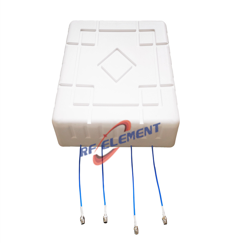
5G NR is built on OFDM, which packs data into narrowly spaced subcarriers and lets the scheduler assign them in fine granularity. The antenna-side consequence is rarely explained: because the same panel must carry several bands with different propagation behavior, a serious 5G antenna is not specified by a single gain figure but by a per-sub-band table. Our 5G small cell 4x4 MIMO panel splits its 617-4200 MHz range into five sub-bands and publishes gain, VSWR, and horizontal beamwidth for each one — 7.5 dBi down at 617-806 MHz where coverage, not capacity, is the goal, rising to 10.5 dBi in the 3.3 GHz and higher sub-bands where capacity lives. If a datasheet quotes one number for a multi-band panel, the vendor is hiding the rows that matter.
Wideband operation and the 6:1 tuning problem
The flexible frame design in 5G NR — variable subcarrier spacing, adjustable slot lengths — lets one network serve low-rate IoT traffic and gigabit users side by side. The antenna equivalent of that flexibility is bandwidth, and it is the hardest electrical problem we handle. Feeding a panel across a 6:1 ratio, from 617 MHz to 3800 MHz, while holding VSWR below 1.8 is where most designs fail at the band edges. Our ultra-wideband MIMO panel was tuned through several radiator revisions to hold 9.8-11.5 dBi across that entire sweep, and it exists as a custom solution precisely because a standard narrowband design cannot be stretched that far by widening a few slots.
MIMO: from 2x2 to 4x4 in the same housing
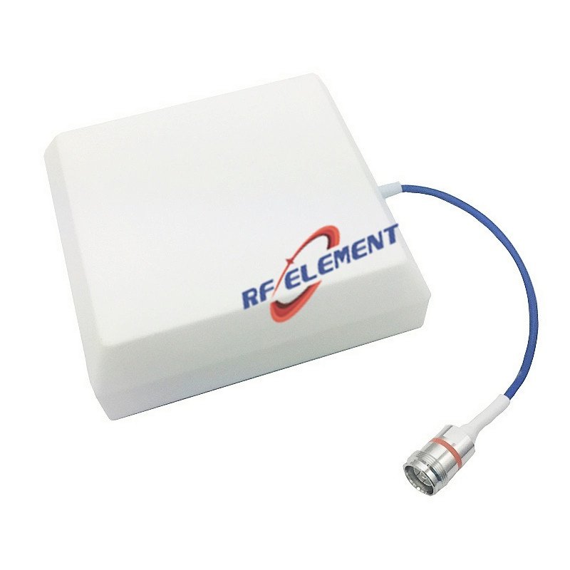
5G carried MIMO forward from LTE and raised the stakes: spatial streams multiply once the antenna can keep them apart. Two requirements follow. First, port count — the small cell panel above carries four 4.3-10 connectors in a 450 × 110 mm radome weighing 2.5 kg, with port isolation specified at 15 dB or better and 18 dB in the mid-band, so the radio's four streams stay separable. Second, pattern integrity — the ±45° cross-polarized arrangement keeps both polarizations usable at the cell edge. Our two-port low PIM MIMO panel covers 698-3800 MHz with 6 dBi of gain and a −150 dBc @ 2×20 W intermodulation rating, which matters the moment a 4x4 or 2x2 radio sits next to other transmitters on the same structure. Carriers that only run the 3.3-3.8 GHz n78 block can skip the wide panels and use a dedicated 3.5 GHz n78 MIMO panel instead — 12 dBi in a 65° horizontal beam, one sub-band, no compromise rows.
Beamforming and what it demands from the radiator
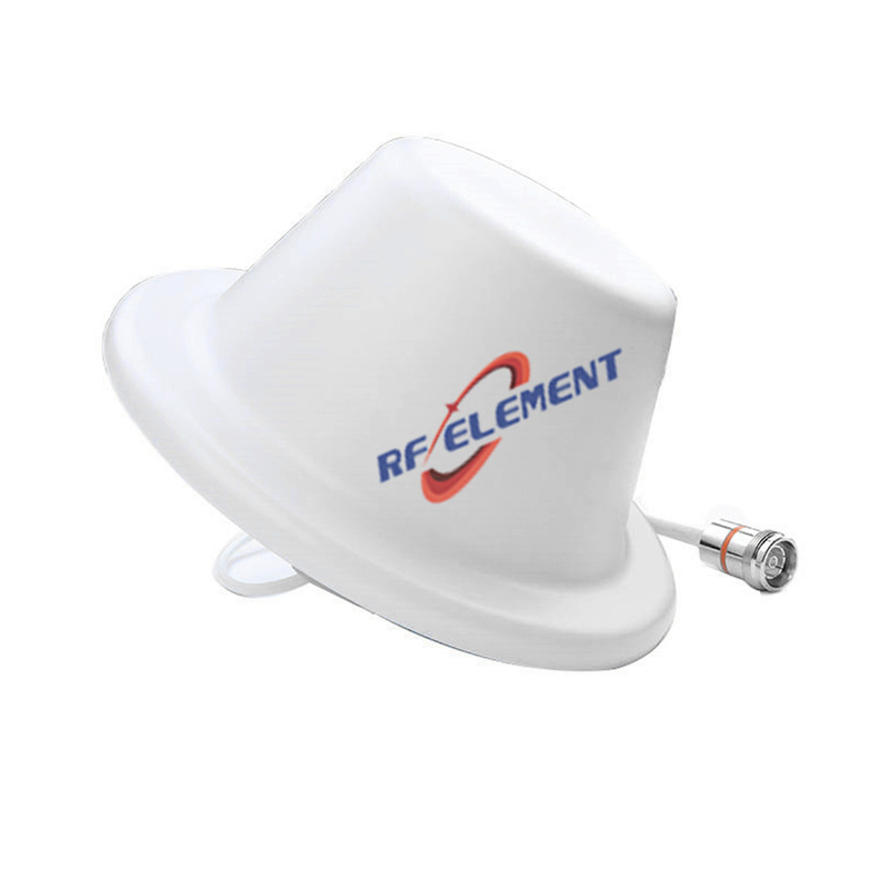
Massive MIMO arrays at the base station steer energy electronically, and the headline deployments use 64 or more elements inside the AAU itself. That does not make the external antenna passive baggage — it changes what is measured. Beamwidth consistency across sub-bands is what lets the network plan cell borders: the small cell panel holds an 80° horizontal beam at low band tightening to 40° at 3.3-4.2 GHz, a controlled narrowing that the propagation model has to know about. A radiator whose beamwidth wanders unpredictably between bands turns every network simulation into guesswork, which is why we publish the per-sub-band beamwidth column instead of a single headline figure. For indoor deployments where the directionality of a panel is unnecessary, the same sub-band discipline carries into the compact ceiling line, which trades the 180° panel pattern for a 12 mm tall omnidirectional footprint.
Where a 5G antenna is the wrong choice
Single-band legacy sites — if the service plan stops at LTE 1800 MHz, a 698-4200 MHz panel pays for sub-bands nobody transmits on; a dedicated single-band unit is cheaper and often performs better at that one frequency — the 1-port directional low PIM panel exists for exactly this kind of narrow assignment.
PIM-sensitive sites with legacy hardware — a −150 dBc panel next to an old, untuned feeder cable is wasted money; remediate the cable first, then upgrade the antenna.
Indoor omnidirectional zones — a panel aimed down a corridor is the right tool for a hallway, but for an open square room the ceiling omni gives more even coverage per unit; forcing a directional panel there creates hot spots under the antenna and dead zones at the walls.
Ordering and what we send back
We manufacture the panels above in ZhaoQing and tune variants for connector type, radome size, and sub-band emphasis on request. Email sales@rfelement.com with the band list, the radio's port configuration, and the mounting envelope, and our reply includes the model match, the per-sub-band table, and a drawing set. Sample units typically ship within 3-5 working days so the numbers can be verified on your own site before volume commitment.
TAG:The Role of 5G Antennas in Key 5G Technologies https://www.rfelement.com