Using Laser Cutting to Rapidly Produce LoRa Antenna Arrays
A LoRa array is a mechanical object before it is a radio. The gain, the beam shape and the match a gateway sees are consequences of how accurately somebody cut the metal, and at 868 and 915 MHz a millimetre of dimensional error already moves the resonant point of a narrow element. We build LoRa omni antennas and the plate hardware that surrounds them, and laser cutting is one of the tools that decides whether a design survives the trip from the model to the mast.
Why the sub-band, not the protocol, sets the geometry
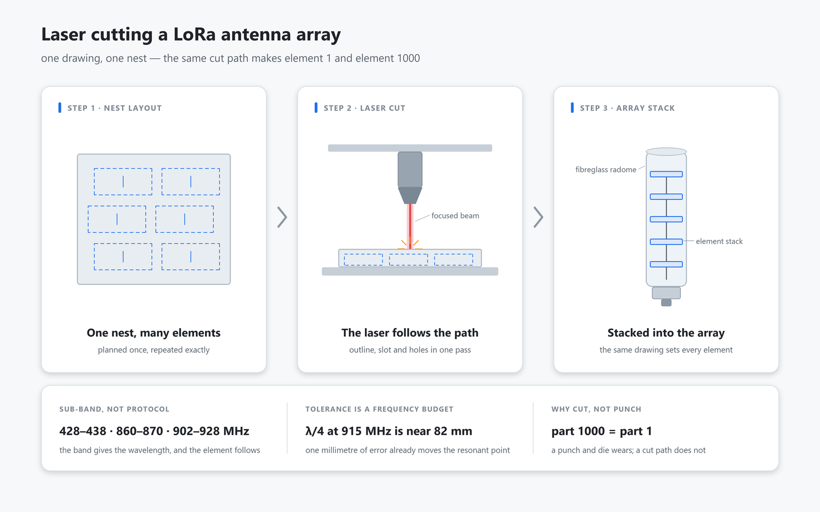
LoRa describes how a packet is encoded, not where in the spectrum it travels. The parts we ship are named by sub-band for exactly that reason: 433 MHz inside 428-438 MHz, 868 MHz inside 860-870 MHz, 915 MHz inside 902-928 MHz. A customer who orders an antenna for the protocol has ordered nothing that can be cut, because no drawing can be generated from an encoding scheme. A customer who names the sub-band has given us the wavelength, and the wavelength decides the element length, the depth of the ground plane behind it and how much of a mast the finished product will occupy. That is why our own part names carry the band rather than the network they will serve, and why a 902-928 MHz radiator is not a 860-870 MHz radiator with a different label.
What the process contributes
Laser cutting removes material from flat stock along a programmed path. In antenna work that path is an outline, a slot or a set of mounting holes, and the value is not speed. It is that the thousandth part is cut like the first, because nothing in the machine wears the way a punch and die wear. A 433 MHz omni antenna and a taller 433 MHz part look alike in a photograph and are not interchangeable. The one we build runs from 428 to 438 MHz with 5 dBi of gain, its energy spread over a 30 degree vertical beam, mounted on a grey fibreglass tube of 20 mm diameter and 1200 mm length that weighs 2.5 kg. Inside each, the radiator length was fixed by a drawing, and a drawing is worth only what the process holds of it.
Tolerance is a frequency budget
At 915 MHz a quarter wavelength sits near 82 mm. A tenth of a millimetre is a small number against the feature that sets resonance, but a large one against a plated layer whose thickness is measured in microns, and it is at that scale that a cut part and a cast part stop being comparable. Two plates cut from the same nest can be married to different radomes and still match, because the geometry that decides the pattern was fixed once and then repeated. Punch a plate instead and hole positions drift as the tool wears. Drift is invisible in a single unit and expensive across a thousand, which is why the process choice belongs to the volume, not to the drawing alone.
Feeding an array
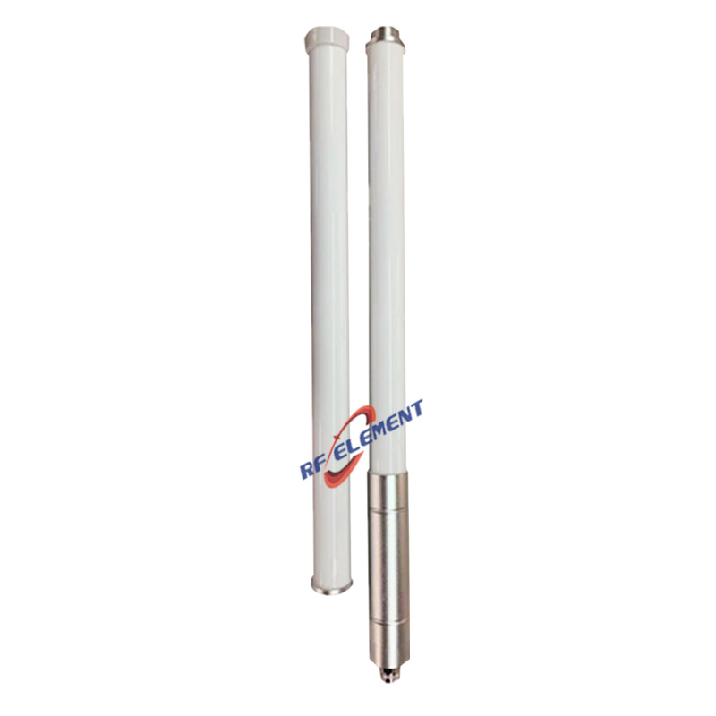
An array is worth nothing if the network feeding it is inconsistent. Every element of a corporate feed carries a share of the input, and those shares are set by line lengths and pad geometry that a cutter reproduces exactly. LoRa does not ask for a phased array, but it does ask for repeatability, because a gateway judges a packet against the ones it did not receive, and a two-element array with a mismatched feed performs worse than a single well-matched element. Our detachable LoRa omni holds VSWR under 1.5 into 50 ohm on both the 868 and the 915 sub-bands, gives 8 dBi of gain, stands 1200 mm tall on a 38 mm fibreglass tube at 3.5 kg, and comes apart into two sections, which lets the radiator be carried separately from its base.
Cutting a slot instead of an outline
A slot antenna is the clearest case for the process. The radiating feature is a gap of a defined width and a defined length in a ground plane, and both dimensions are set by the cut rather than by a formed edge. A pair of slots fed a quarter wavelength apart behaves differently from the same pair fed a half wavelength apart, and neither behaviour can be dialled in on the bench if the two gaps are not cut to the same width along their whole length. The same reasoning carries over to the vertical arrays we mount inside fibreglass tubes: the element stack is set out on one sheet, cut as a single nest, and then the only variable left in production is how the stack is clamped, not how accurately the elements were made.
What the finished hardware looks like
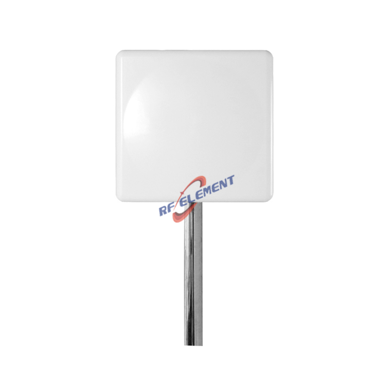
The range we build on the back of this process is narrow in band and honest about it. A 900 MHz omni antenna spans 824 to 960 MHz with 5 dBi of gain, its energy spread over a wide 35 degree vertical beam, in a grey housing 20 mm in diameter and 600 mm long that weighs 1.0 kg. An IoT omni antenna puts 8 dBi into 900-930 MHz through a 16 degree lobe on a 42 mm tube 1540 mm tall at 1.5 kg, which is what a mast in open country is for. Above that band the same geometric rules apply with shorter elements: a 5G n78 fibreglass omni reaches 11 dBi across 3400-3800 MHz in an 8 degree lobe from a 42 mm body 630 mm long at 1.0 kg. Where the array lives inside a housing rather than on a mast, the element itself is often a die-cast aluminium radiator at 53 by 53 by 40 mm and 26 g, sandblasted and electroplated, because a cast part carries its mounting bosses in the same shot. The two processes are not rivals in that sentence: an array whose elements are cut and whose housing is cast is the ordinary arrangement, and the drawing pack for it is two drawings rather than one. What matters is that the drawing which sets the pattern is the one the cutter works from, so the tolerance chain starts at the machine rather than at the assembly bench.
Where laser cutting is the wrong choice
The process stops paying the moment the part stops being flat. A waveguide throat has to be machined, because its internal dimensions settle which mode can propagate, and a cut face will not hold them to the tolerance that requires. A sealed outdoor housing is usually a casting, since draft angles and wall thickness belong to a mould rather than a sheet. High volumes of a small flat part go to a punch and die once the tool cost can be spread across the order, and a bracket that has to be formed first and finished afterwards is a sequencing problem that a cutting machine on its own cannot settle. Thick plate and highly reflective stock cost more to cut than to machine, and the finish a customer asks for, whether anodised, painted or electroplated, is settled before the blank exists. If the annual volume is in the hundreds rather than the tens of thousands, cutting is usually the cheaper answer; if it is in the hundreds of thousands, we will say so rather than quote against a process that will not survive the second year. The same discipline applies one level up: our guide to LoRa antenna design sets out what to fix on paper - band, envelope, mount and quantity - before a process route or a finished part is quoted.
What to send us
Tell us the material, the sheet thickness, the annual quantity and how tight the tolerance really has to be, and attach the drawing with its datum marked. Put those four in a single note to sales@rfelement.com and expect a process route back rather than a machine list. If the layout is still moving, say that too, because choosing a route costs less while the dimensions are open than it does once a prototype has been cut and measured. The housing is the other half of that decision, and keeping it beside the cutter is the ordinary arrangement; what an antenna and enclosure from one plant changes is set out in our design-to-die-casting article.
TAG:Using Laser Cutting to Rapidly Produce LoRa Antenna Arrays https://www.rfelement.com