Sector Antenna vs Panel Antenna: Which Fits Your Site?
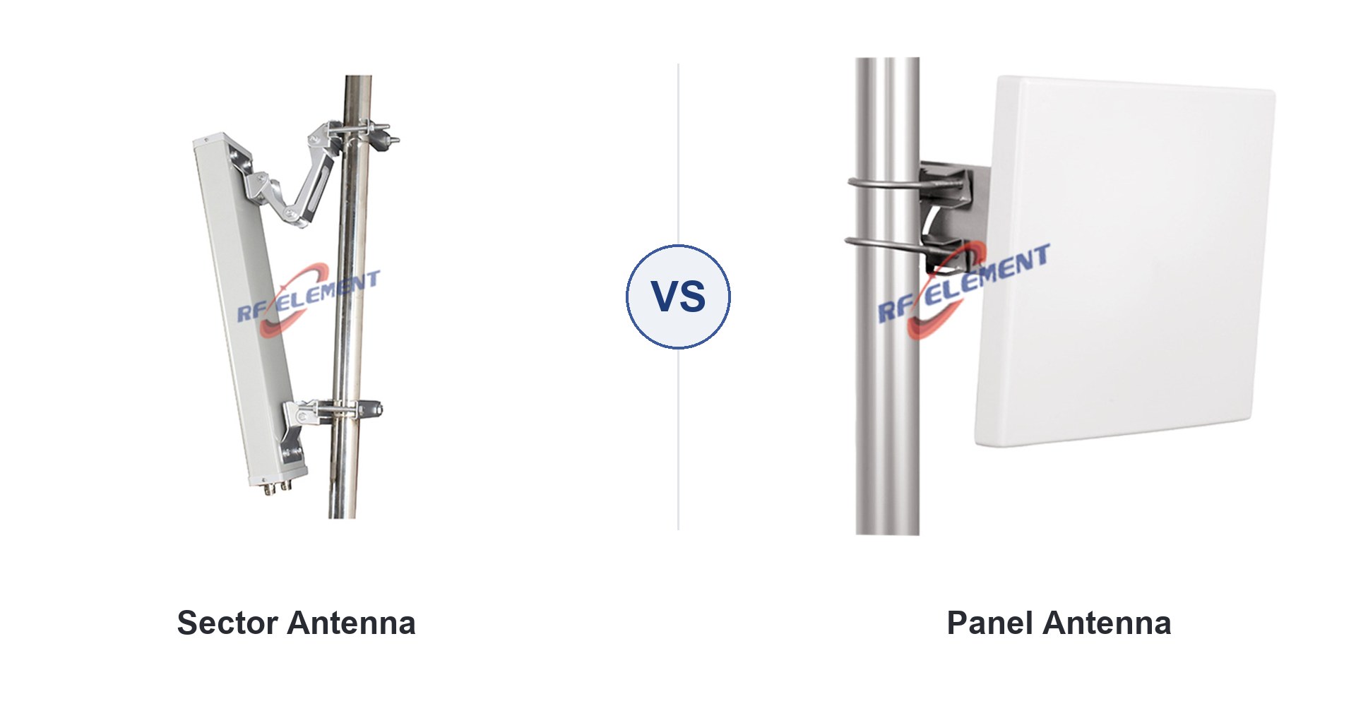
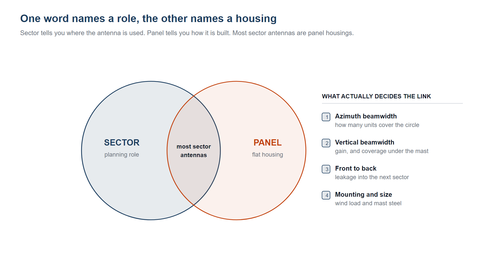
A sector antenna covers one slice of a site, usually 60 to 120 degrees; a panel antenna is a flat housing that can serve any arc. In practice most sector antennas are panel antennas, so the label alone tells you nothing about beamwidth, gain or mounting.
The two words come from different places. Sector is a planning term: a site is divided into sectors, and each sector needs an antenna aimed at it. Panel is a construction term: a flat array behind a sealed radome. A catalogue page that says sector is telling you where the antenna is meant to be used. A page that says panel is telling you how it is built. Neither word sets the numbers that decide whether the link closes.
This guide separates the two, then shows where the real differences sit: azimuth and vertical beamwidth, gain at a stated band, front-to-back ratio, ports, and the mechanical load on the mast. Three production units are used as worked examples so the comparison stays on measured figures rather than catalogue adjectives.
What is a sector antenna?
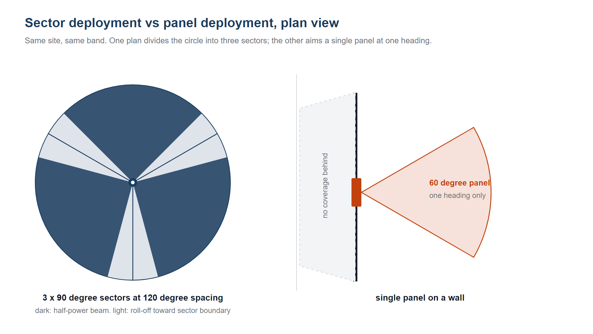
Sector is about coverage geometry. A three-sector site places three antennas at 120 degree spacing and expects each one to cover its own third of the circle. A six-sector site does the same with 60 degree spacing. The antenna is called a sector antenna because of that job, not because of a particular internal design.
What is a panel antenna?
Panel is about the radiator. A flat panel is an array of elements behind a flat radome, fed by one or two ports. It produces a directional pattern whose width is set by the aperture in each plane. That housing can be built for 120 degrees of azimuth or for 30 degrees, with a vertical beam of 6 degrees or 60 degrees, at 700 MHz or at 3.5 GHz.
Why the two labels overlap
The overlap is large. Most antennas sold as sector antennas are panel antennas in a weatherproof radome with a pole bracket. Some antennas sold as panel antennas are used exactly like sector antennas, because their beamwidth and front-to-back ratio suit a sector plan. The useful question is not which label the page uses, but which of the numbers below it publishes.
What actually differs in the datasheet
Set the label aside and compare the attributes that decide the link. Every entry below assumes a stated band and a stated vertical beamwidth, because gain cannot be compared across bands and a horizontal figure alone says little about coverage on the ground.
| Attribute | Usually sold as sector | Usually sold as panel | Why it matters |
|---|---|---|---|
| Azimuth beamwidth | 65 to 90 degrees, 120 degrees at 2.6 GHz and below | 30 to 90 degrees, indoor units often 60 to 90 | Sets how many units cover the circle and where the edges overlap |
| Vertical beamwidth | 7 to 18 degrees, with a downtilt bracket | 25 to 60 degrees on short links and indoor units | Sets gain, and sets whether there is a hole under the mast |
| Gain at a stated band | 12 to 18 dBi at 1.8 GHz, vertical 7 to 18 degrees | 8 to 14 dBi at 1.8 GHz, vertical 25 degrees or wider | Follows the angles, never the label |
| Front-to-back ratio | 20 to 25 dB | 15 to 20 dB, or better with a wall behind it | Stops one sector from leaking into the one behind it |
| Housing and mounting | Sealed radome 0.9 to 2 m tall, pole clamp, tilt bracket | Compact radome 0.2 to 0.5 m, wall bracket or short pole | Sets wind load, ice load and how much mast steel is needed |
| Ports and polarisation | 2 ports common, single or dual polarised | 2 ports common, dual or circular polarised | Sets whether 2x2 MIMO or cross-polar isolation is available |
The gain row is the one that gets misread. At the same band and the same vertical beamwidth, a 65 degree panel and a 65 degree sector antenna have the same directivity, because directivity depends on the two angles and on nothing else. If a sector unit shows 3 dB more than a panel unit, the vertical beam is narrower, not the label better.
Three production units, one table
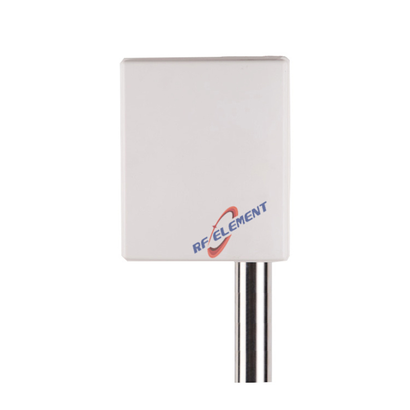
The clearest way to see the split between role, housing and numbers is to line up real hardware. All three units below are built in flat radomes with two N-Type female ports. Two are sold as sector antennas and one as a panel antenna.
| Model role | Band | Azimuth x vertical | Gain | Front to back | Housing |
|---|---|---|---|---|---|
| 90 degree 4G LTE sector | 698 to 2700 MHz | 90 x 18 degrees low band, 90 x 9 degrees high band | 12 dBi and 15 dBi | above 20 dB | 900 x 325 x 140 mm, 5.5 kg |
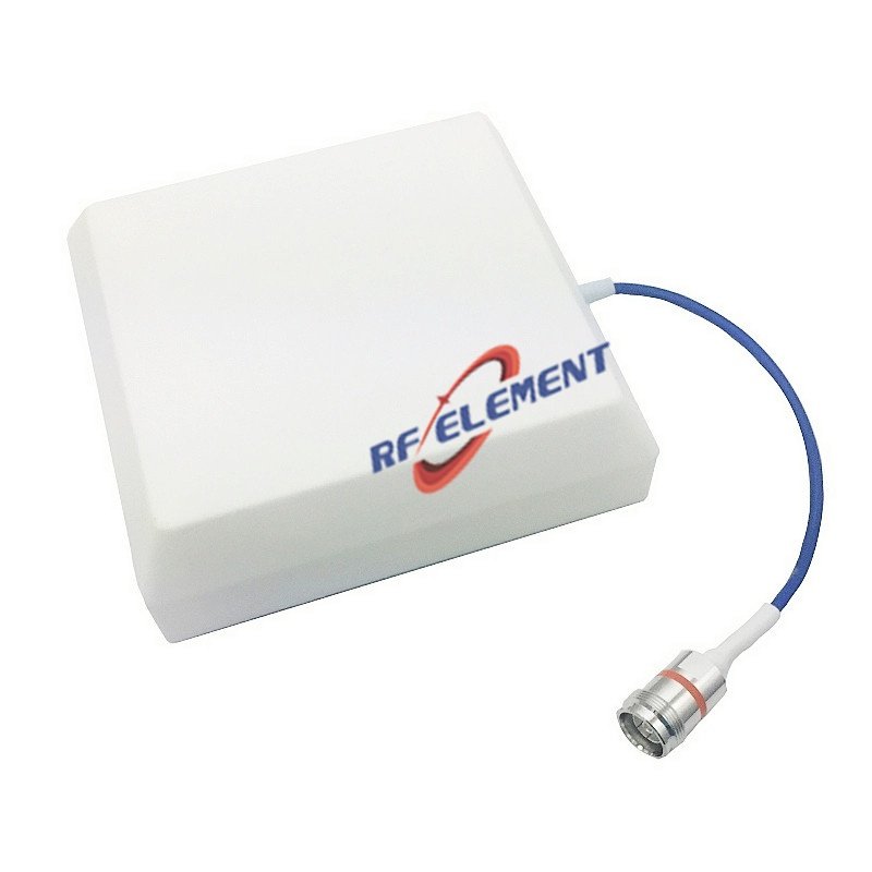
| Cross-polarised sector, plus and minus 45 degrees | 698 to 2700 MHz | 65 x 65 degrees in both sub bands | 7 dBi and 9 dBi | above 20 dB | 450 x 280 x 180 mm, 2.5 kg |
| 5G n78 MIMO panel | 3300 to 3800 MHz | 65 x 28 degrees | 12 dBi | not published for this class | 239 x 190 x 35 mm, 1.0 kg |
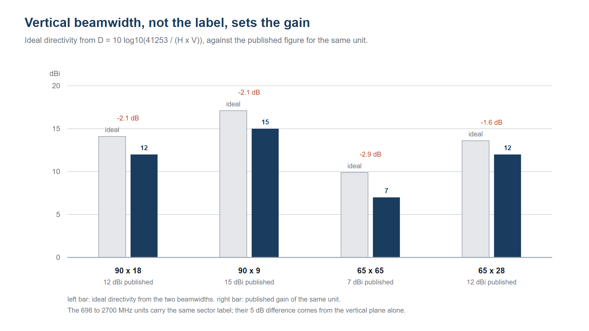
Read the first two rows together, because they carry the same label and different physics. Both are sector antennas for 698 to 2700 MHz. The first holds an 18 degree vertical beam at the low band and returns 12 dBi; the second opens to 65 degrees vertically and returns 7 dBi. That 5 dB gap comes from the vertical plane alone. It has nothing to do with the word sector on the page.
Now compare row one and row three. Both publish 12 dBi, but they are not the same antenna at all: one is a 900 mm tall low-band sector, the other a 239 mm panel for 3.5 GHz. The panel is smaller and lighter because the wavelength is shorter, not because a panel is inherently more efficient. A 12 dBi figure without its band is a number without a unit of meaning.
Gain follows the angles, size follows the band
Two relations keep the comparison honest. Directivity comes from the two beamwidths, both in degrees:
D = 10 x log10 ( 41,253 / (H x V) )
Physical aperture comes from the beamwidth and the wavelength together, at roughly 70 wavelengths divided by the angle for a tapered aperture:
Width = 70 x wavelength / H, height = 70 x wavelength / V
Run the three units through both. The 90 x 18 degree unit has an ideal directivity of 14.1 dBi and publishes 12 dBi, about 2 dB of aperture efficiency loss. The 90 x 9 degree unit works out at 17.1 dBi and publishes 15 dBi, the same 2 dB. The 65 x 65 degree unit works out at 9.9 dBi and publishes 7 dBi, close to 3 dB down, which is what a compact 280 mm radome returns when asked for a wide vertical beam at the bottom of the band. The 65 x 28 degree n78 panel works out at 13.6 dBi and publishes 12 dBi.
The size column tells the rest of the story. A 65 degree azimuth pattern at 700 MHz needs an aperture near 0.46 m before the vertical plane is even considered. The same 65 degree pattern at 3.5 GHz needs about 0.09 m. This is why a low-band sector antenna is a metre of radome on a pole and a 3.5 GHz panel fits in one hand. When a buyer says panels are smaller, what they usually mean is that the panel in front of them works at a higher frequency.
Mounting, downtilt and wind load
The mechanical difference is real even when the RF difference is not. A sector antenna for a macro site is normally clamped to a pole with a bracket that allows mechanical downtilt of a few degrees, and it is tall enough to hold a narrow vertical pattern. The 900 mm unit above weighs 5.5 kg and presents a large flat face to the wind. A panel for indoor or short-link work is usually wall-mounted on a small bracket, weighs around a kilogram, and has a face measured in a few hundred millimetres.
Wind load scales with frontal area and with the square of wind speed, so the tall radome carries most of the structural cost on an exposed mast. That cost is justified when the site needs 15 dBi and an 18 degree vertical beam. It is wasted when the antenna is covering a corridor from a ceiling. The same logic applies to ice: a wide flat face collects it, a small panel does not.
Downtilt deserves a separate line. A sector site uses downtilt to place the vertical pattern on the ground rather than at the horizon, and the tilt has to match the site height and the cell radius. A wall-mounted panel in an indoor space usually has no tilt mechanism at all, because the geometry is short and the pattern is wide. Comparing a tilted macro sector with an untilted indoor panel on gain alone misses the reason each one exists.
The sector edge and the front-to-back ratio
In a three-sector plan, the place where performance is decided is the boundary between sectors. A 90 degree unit reaches its half-power edge 45 degrees off boresight; a 65 degree unit reaches it at 32.5 degrees. With 120 degree boresight spacing, the 65 degree unit leaves a 27.5 degree gap on each side that has to be covered by overlap or accepted as a softer edge, while the 90 degree unit arrives within 15 degrees of the boundary. That is the trade covered in the 65 vs 90 degree sector beamwidth comparison, and it does not change because an antenna is labelled panel.
Front-to-back ratio is the other half of the boundary story. Both 698 to 2700 MHz units above are specified above 20 dB, which keeps energy from wrapping around the mast into the sector behind. A panel mounted flat on a wall gets extra isolation from the wall itself, which is one reason indoor panels can publish a lower figure and still behave well in service.
When a panel housing is the wrong choice
If the site is planned as three sectors and the antenna has to hold a narrow vertical beam with controlled downtilt, a compact panel is the wrong tool. Not because of its label, but because its vertical beam is wide, its gain is low for the arc, and it has no tilt bracket. Put one on a macro pole and the pattern lands where the geometry does not want it: too much energy close in, too little at the cell edge, and no way to adjust.
The second wrong case is capacity. A sector that has to hold a 2x2 cross-polarised link at the cell edge needs port isolation and a clean pattern at the edge, and that comes from a purpose-built sector radome, not from a small flat panel aimed at the same heading.
When a sector housing is the wrong choice
The reverse case is just as common. A corridor, a single wall, a donor link to a repeater, or a small cell on a lamp post does not need a metre of radome. The 239 mm n78 panel above covers 65 by 28 degrees at 3.5 GHz with 12 dBi and weighs a kilogram, which is the right order of hardware for a pole that was not built to carry a macro antenna. Specifying a sector housing there buys wind load and cost with no link budget gain.
Indoor work is the clearest example. Ceiling height limits the useful downtilt, the link distances are short, and the pattern that fills a hall is wide in both planes. A compact panel, or a dedicated indoor unit, does that job. A macro sector antenna mounted indoors is a structural problem looking for a reason.
Specification checklist
Before the purchase order goes out, confirm these points against the site plan:
Sector count and boresight spacing, so the azimuth beamwidth matches the reuse pattern rather than the catalogue page.
Vertical beamwidth and the downtilt range available, checked against site height and cell radius.
Gain quoted with its band and its vertical beamwidth, so two candidates can be compared on equal terms.
Front-to-back ratio at the band in use, especially where the antenna sits close to a sector behind it.
Port count, polarisation and isolation, if the site runs 2x2 MIMO or cross-polar diversity.
Radome size, weight and frontal area, against what the mast or wall was designed to carry.
Mounting hardware, including whether a tilt bracket is supplied or has to be ordered separately.
Band coverage at the edges, not only at centre frequency, since a 698 to 2700 MHz unit has to hold its pattern at both ends.
If the site is a three-sector macro build, start from the sector plan and work back to the antenna. If it is a wall, a corridor or a lamp post, start from the housing that fits the structure. Either way, the numbers on the datasheet decide the link, and the label only tells you which page of the catalogue to open.
Frequently asked questions
Can a panel antenna replace a sector antenna?
Yes, if its azimuth beamwidth, vertical beamwidth, front-to-back ratio and mounting suit the sector plan. A 65 by 28 degree panel with 12 dBi can serve a sector at 3.5 GHz, which is the format covered in our 5G antenna range. It cannot replace a 900 mm low-band sector that has to hold an 18 degree vertical beam and 15 dBi at 1.8 GHz, because the angles and the aperture are not there.
What beamwidth should a three-sector site use?
Ninety degrees is the usual starting point, because three 90 degree patterns at 120 degree spacing leave a workable overlap at the boundaries. Sixty-five degrees gives about 1.5 dB more directivity at the same band and vertical pair, at the cost of a wider gap at each edge that has to be managed with tilt and aiming. One hundred and twenty degrees is common at 2.6 GHz and below, where a wide arc matters more than gain.
Does higher gain always mean better coverage?
No. Gain comes from narrowing the pattern, so a higher figure means a smaller footprint on the ground. A 15 dBi sector with a 9 degree vertical beam covers a shorter radial distance than a 12 dBi unit with an 18 degree beam when both are mounted at the same height, because the beam hits the ground sooner. Coverage is set by the pattern shape, the tilt and the site height, not by the dBi number alone.
If you are choosing between a sector housing and a panel for a specific site, send the sector plan, the band and the mounting height to our engineering team. We will come back with the pattern that fits the plan and the datasheet that proves it.
TAG:Sector Antenna vs Panel Antenna: Which Fits Your Site? https://www.rfelement.com