
Picking a 4G LTE antenna is a three-variable decision: where it mounts, how far the signal must reach, and how many ports the radio needs. Our catalogue covers 698-2700 MHz across both variables — from a 0.4 kg ceiling dome that hides above a tile to a 5.5 kg, 15 dBi sector that serves a cell edge. This page walks through the decision with the actual catalogue numbers, so the choice can be made from a datasheet instead of a guess.
Step 1: fix the mounting point first
Indoor builds start with the ceiling. Our 4G LTE ceiling antenna covers 698-2700 MHz with 3 dBi gain, VSWR at or below 1.5, and a 50 W rating on one N-type female port. The radome is 185 mm across and 90 mm high at 0.4 kg, radiating 360° in azimuth. At 3 dBi the coverage cell is modest by design — the antenna is the last metre of a distributed antenna system, not the link itself.
Outdoor builds put the antenna where the cable run and the tower height are cheapest, and that is where the gain ladder begins.
Step 2: omni or sector
Omnidirectional. Three outdoor omnis span the need range:
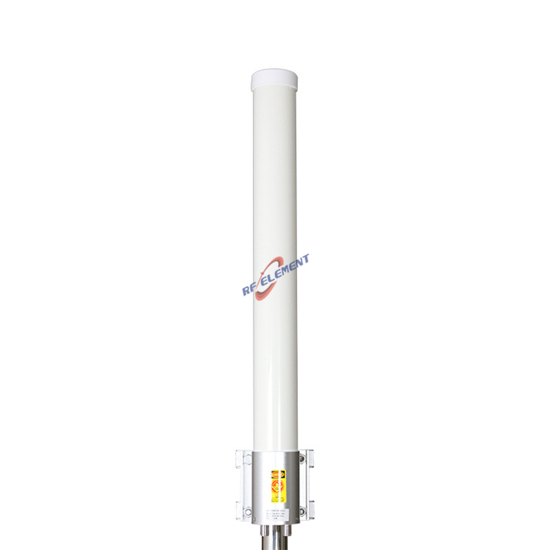
The 4G LTE MIMO omni antenna for 698-2700 MHz is a 2.0 kg fiberglass radome, 75 mm across and 700 mm long, with two N-type ports and VSWR at or below 2.0. Point-to-multipoint feeds and small cell sites are its natural home.
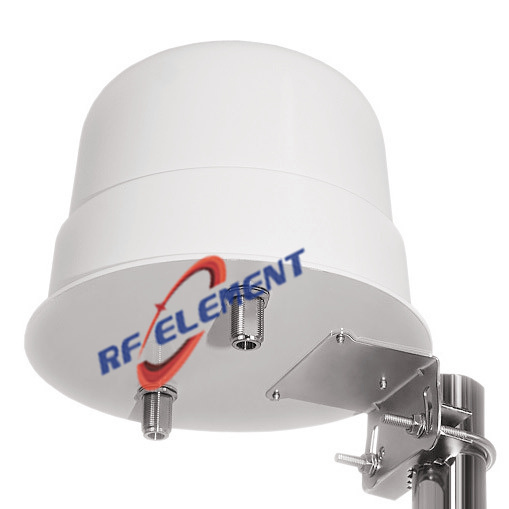
The dome omni for 800-2600 MHz runs 4 dBi with ±45° polarization, two ports, VSWR at or below 1.8, in a 210 mm × 150 mm housing at 1.0 kg.
The outdoor low-PIM omni holds 3rd-order PIM to -150 dBc at 2×20 W, gain 4 dBi, one 7/16 DIN port, in a 52 mm × 1200 mm radome at 2.5 kg. This is the unit for shared infrastructure where several operators inject power into the same antenna.
When a site needs four radio chains on one radome, our 4-port 4G LTE omni stacks two omni sets vertically to reach 4-6 dBi per port across 698-2700 MHz with four N-type female connectors and VSWR below 1.8.
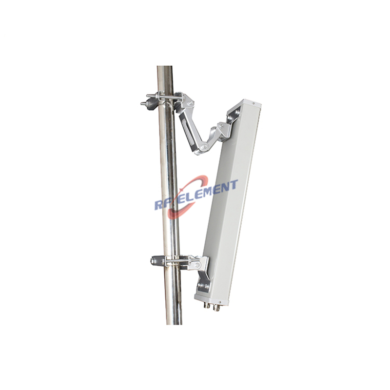
Sector. Where the traffic is — along a road, across a yard, at the edge of a camp — a sector concentrates the radiated power. Our 90-degree LTE sector antenna delivers 12 dBi across 698-960 MHz and 15 dBi across 1710-2700 MHz, with a 90±5° horizontal beam, front-to-back ratio above 20 dB, 100 W handling, and two N-type ports in a 900 × 325 × 140 mm enclosure at 5.5 kg. The ±45° cross-polarized MIMO sector packs 2×2 MIMO into a 65±5° beam at 2.5 kg — half the size, both polarizations on one reflector.
Step 3: count the ports before you buy
MIMO capacity comes from ports, not from gain. One port moves one spatial stream; the 2-port dome and fiberglass omnis drive 2×2 radios; the 4-port omni serves 4×4. Match the port count to the radio's connector plan first — adapter chains between an N-type antenna and an SMA radio lose more than they look like they would on paper.
Step 4: check the PIM budget on shared sites
On a tower where two or three carriers share the antenna, intermodulation products land right inside the receive band. The low-PIM omni above is specified at -150 dBc with 2×20 W carriers, and the ceiling domes we ship for DAS carry the same class of rating. Single-operator, single-radio installations rarely need to pay for that headroom.
Cable and connector notes
Two connector families run through the line: N-type on the domes, omnis, and sectors, and 7/16 DIN on the low-PIM unit, where higher power and tighter passive-intermodulation control matter. Keep the adapter count between antenna and radio at zero when the site plan allows — every extra interface is both a PIM source and a water-ingress point, and a mast-head adapter two storm seasons in is the failure nobody logs. Also price the cable before the gain: a long, thin run can eat more dB than the difference between an omni and a sector, so the budget that counts is measured at the radio port, not at the antenna flange.
Where each choice is the wrong choice
A sector on a city-centre rooftop with subscribers on all sides wastes 12-15 dBi of gain on directions nobody is in; take the omni.
An omni on a 10 km point-to-point hop dilutes the link budget over 360°; take the sector.
The 4-port omni on a 2-port radio leaves connectors sealed and adds wind load for nothing.
The low-PIM unit on a private single-carrier site spends budget the radio plan never uses — fine, but not necessary.
The 0.4 kg ceiling dome as the only antenna on a remote outdoor site: it is an in-building unit, not a cell-edge solution.
Quick reference
| Need | Model family | Band | Gain | Ports |
|---|---|---|---|---|
| In-building coverage | Ceiling dome | 698-2700 MHz | 3 dBi | 1 |
| Outdoor area feed | Fiberglass MIMO omni | 698-2700 MHz | 2 ports, VSWR ≤2.0 | 2 |
| Shared tower, strict PIM | Low-PIM omni | 698-2700 MHz | 4 dBi, -150 dBc | 1 |
| Four radio chains | 4-port omni | 698-2700 MHz | 4-6 dBi | 4 |
| Cell edge, one direction | 90° sector | 698-2700 MHz | 12/15 dBi | 2 |
| Sector + MIMO, compact | ±45° cross-pol sector | 698-2700 MHz | 65±5° beam | 2 |
Ordering, samples, and what we send you
Every model above is manufactured in-house at ZhaoQing, and the OEM/ODM path is open on all of them: connector swaps, cable lengths, mounting hardware, radome colour, and re-tuned gain or beamwidth on the same platform. We dispatch samples in 3-5 working days; bulk orders run on a 15-25 working day production plan, and MOQ starts low enough for a single-site pilot. Message sales@rfelement.com with the deployment checklist above — mounting point, band plan, port count, and site type — and we will return the matching datasheet, the mechanical drawing, and a sample unit for the trial. For shared-site builds, include the carrier mix and we will state the PIM figure the installation should be held to.
TAG:Choosing the Right 4G LTE Antenna https://www.rfelement.com