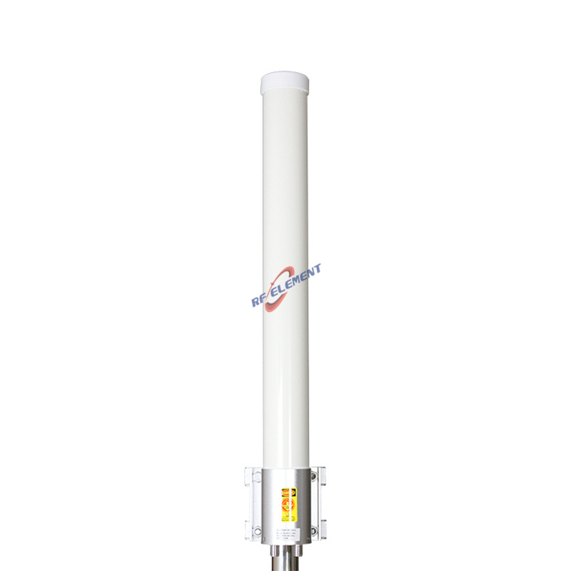
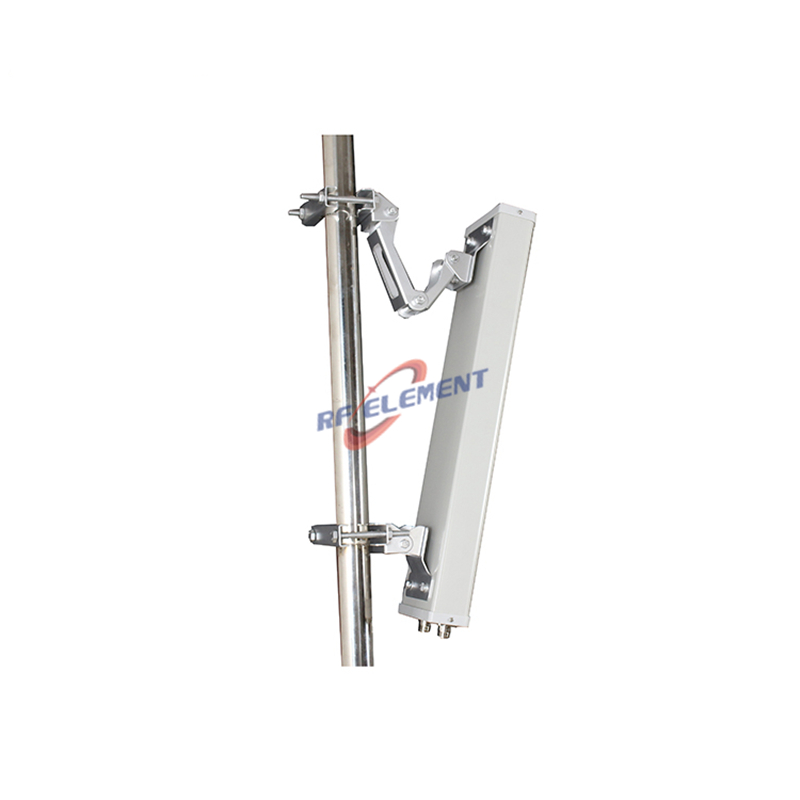
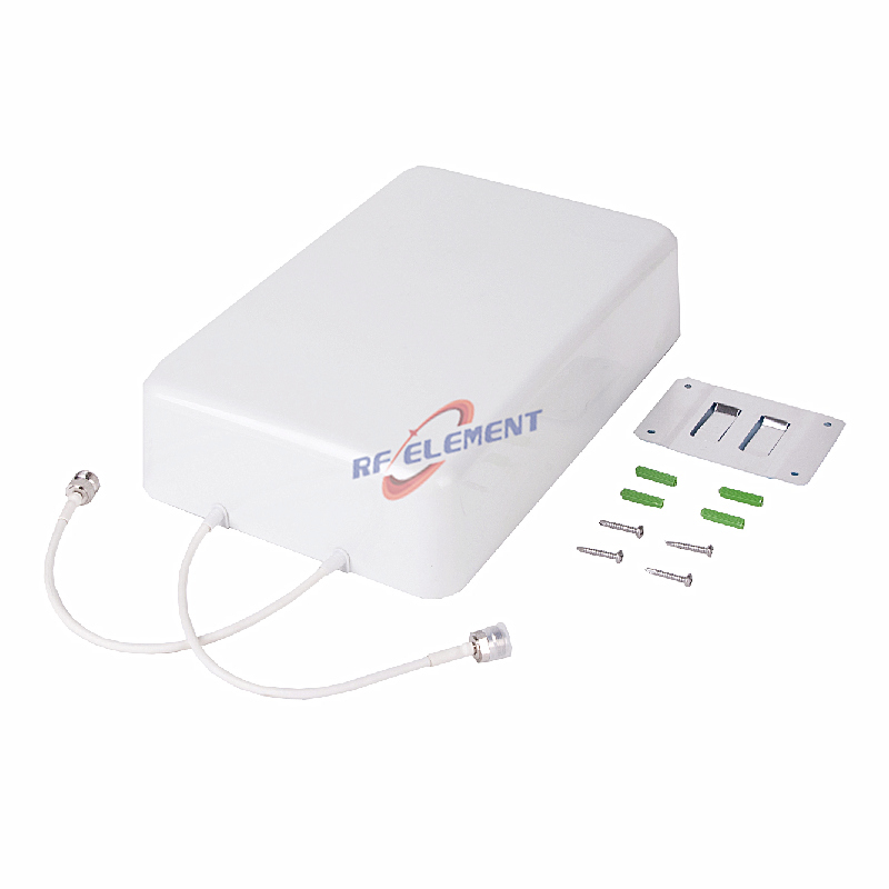
The Role of 4G LTE Sector Antennas in Enhancing Signal Coverage
A dense urban block is a hostile place to put a radio link indoors. Concrete, glass and the sheer number of walls between the street and the third-floor desk absorb a signal in a way no receiver can compensate for, and the operators who solved the problem did it by changing the shape of the coverage rather than the power behind it. The sector antenna is that change: instead of broadcasting in every direction from a rooftop, it aims a defined slice of energy at the streets and blocks that actually need it. We build those antennas, and this is how we go through a coverage plan with the customers who deploy them.
Why an omni loses in a city
An omni spreads its power across 360 degrees, which is the correct answer on a rural mast where users arrive from every direction and the nearest neighbour is a field. In a built-up area the same pattern wastes most of its energy, and that waste is not neutral: it lifts the interference level seen by every neighbouring receiver, including the operator's own. A sector fixes the accounting. Concentrating the same transmitter power into a 90-degree slice raises the effective radiated power in the direction that matters, and leaves the other three quadrants alone. The gain printed on the datasheet is only the visible half of that trade; the interference reduction is the half that shows up in the drive test.
Picking the beamwidth: the arithmetic of a three-sector plan
A 90-degree outdoor sector is the standard building block of a three-sector rooftop: three of them cover a full circle with a deliberate overlap at the edges, where handover happens. Its continuous 698-2700 MHz coverage, 12 dBi of gain, a 90±5° horizontal and 18° vertical pattern, more than 20 dB of front-to-back discrimination, 100 W of handling across two N-type female inputs, and a PVC housing measuring 900 by 325 by 140 mm at 5.5 kg are all sized for that job. Narrow the pattern and the plan changes shape: a 65±5° part suits a six-sector ring where each cell carries more traffic on less ground, and the cross-polarized MIMO sector gives that narrower slice two data streams, at 7 dBi from a PVC body of 450 by 280 by 180 mm and 2.5 kg, carrying the same 100 W through a second pair of N-type female inputs and more than 20 dB of front-to-back discrimination.
Cross-polarization is what makes a MIMO sector honest
Two ports do not automatically mean two streams. The ±45° pair on the MIMO sector works because the two polarizations arrive at the receiver along channels that stay sufficiently independent, and the housing and feed network are built so that they do. Where a project pairs that antenna with a single-path radio, the second polarization sits idle and the 5 dB of gain surrendered against the 90-degree part is simply gone. That is a purchasing mistake rather than an engineering one, and it is invisible on a bill of materials.
Tilt, overlap and the seam between cells
Vertical beamwidth sets how much of the coverage plan is settled by the vertical pattern rather than by the azimuth. The 90-degree part spreads its energy over 18 degrees vertically, which on a typical rooftop height reaches the street and the floors above it; the narrower MIMO part spreads over 65±5° in both planes, which is a deliberately rounder pattern for shorter throw distances. Whether that beam is aimed down mechanically or left broad is a decision about the site, not the antenna, but it has to be made before the mount is welded. Cells that overlap too little lose calls at the seam; cells that overlap too much interfere with each other in the same band. The directional purity of both parts — more than 20 dB of front-to-back discrimination — is what stops the sector facing away from a user from arriving at that user's receiver anyway.
Frequency reuse is the real capacity lever
Adding sectors multiplies capacity only if the same spectrum can be used again in a different direction without the two uses hearing each other. Pattern control is what makes that possible: a well-behaved 90-degree sector with a clean front-to-back ratio puts energy where it was aimed and very little behind it, so a planner can repeat the same channel on the opposite face of the same rooftop. When a site runs multiple carriers, the metal path becomes the limit rather than the air path, and passive intermodulation moves to the front of the specification. The low-PIM outdoor panel is built for that case: 698-3800 MHz on vertical polarization at 6 dBi, a 90±15° horizontal and 85° vertical pattern, VSWR within 1.8, front-to-back discrimination no weaker than 10 dB, rated to 50 W through one 4.3-10 female feed, and third-order intermodulation held to -153 dBc under a 2×43 dBm drive, all in an ABS body measuring 165 by 155 by 45 mm, 0.4 kg. On a shared site the intermodulation figure is not a marketing line; it is the reason the site can pass its acceptance test.
Mounting: the part of the plan that is decided on the roof
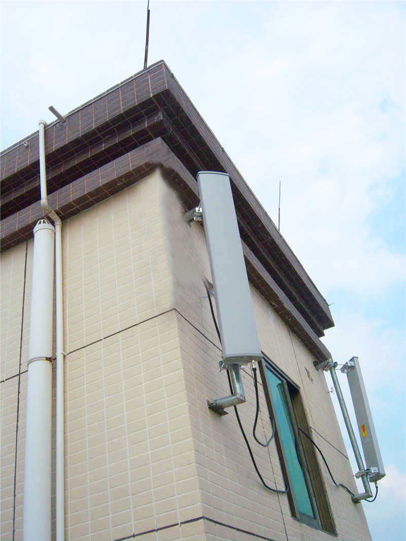
A 5.5 kg sector with a 0.9-metre face is a sail. Pole diameter, bracket capacity and the wall or parapet it is fixed to all have to accept the wind load at the site's exposure, and the azimuth has to be set to the plan rather than to the nearest convenient view. Both sector parts above are pole-mounted with the hardware supplied; the aim is mechanical, so the accuracy of the install is the accuracy of the coverage. We ask for the pole diameter and the intended azimuth with the enquiry, because a sector delivered to a site that cannot hold it aimed is a sector that will be re-aimed by the weather.
Where the wrong choice shows up
The first error is a sector aimed at a problem that is not directional: an indoor car park or a long narrow valley does not reward 12 dBi of front-to-back discipline, and a MIMO omni in the same band spreading 4 dBi over a true 360° circle serves it better from one mounting point. The second is a narrow sector chosen for gain on a rooftop whose mount cannot hold aim: at 65° the pattern tolerates less movement than the bracket does, and the coverage degrades quietly between maintenance visits. The third is the opposite of the point of this article — sectors installed to fix an indoor problem that was really a feeder or a receiver problem, which the new pattern cannot reach.
When the sector is not the answer
Three cases send the enquiry elsewhere. Coverage inside a building belongs to ceiling and panel parts rather than to a rooftop sector. A site that must also carry the low bands into a wide area is better served by the wider 698-4200 MHz wideband panel, which holds ±45° polarization with at least 20 dB of port isolation across the LTE and mid-band 5G span. And where the site is a hotspot rather than a coverage cell, the antenna that matters is an access part — the dual band WiFi sector covers 2400-2500 MHz and the 5.8 GHz band on four N-type female inputs for exactly that role.
What we need to plan a sector site
Send the coverage objective, the rooftop or mast height, the pole diameter, the azimuth plan if one already exists, and the number of ports the radio offers. What comes back proposes the beamwidth and the polarization, attaches the pattern and the specification table, and states the mounting and load assumptions we have used. Evaluation units ship roughly a week from drawing sign-off, production scheduling follows agreed volumes, and the unit minimum allows one sector to be instrumented before a whole ring is committed. Send the enquiry to sales@rfelement.com; the coverage the plan describes is the coverage the drive test will record.
TAG:The Role of 4G LTE Sector Antennas in Enhancing Signal Coverage https://www.rfelement.com