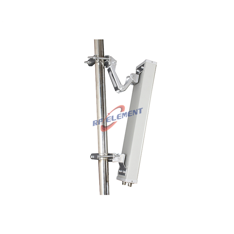
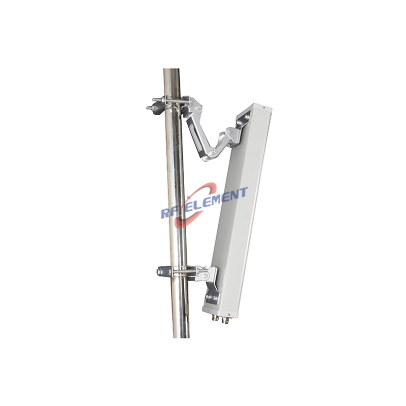
A sectorised antenna — also written sectorized, and more commonly called a sector antenna — is a directional antenna that covers a horizontal slice of typically 30 to 120 degrees rather than the full 360 degrees of an omnidirectional antenna. Three or four of them, pointed outward at different azimuths from the same structure, together provide full 360 degree coverage with far more gain in each direction than any single omni could deliver. That simple division of labour is why the sector antenna is the default choice for cellular base stations, outdoor WiFi access points, and most point-to-multipoint networks.
This guide explains what the term means, how the horizontal beamwidth is chosen, which parameters actually matter on a datasheet, and how to match a sector antenna to common scenarios from macro sites to rail corridors and campus WiFi.
What a sectorised antenna is
A sector antenna restricts its radiation to one azimuthal slice. In the horizontal plane its pattern is roughly a wedge, and the width of that wedge is described by the half-power beamwidth — the angular range over which the radiated power stays within 3 dB of its peak. In the vertical plane the beam is deliberately narrow, which is what concentrates energy toward the horizon or toward a defined coverage area instead of wasting it into the sky.
Most modern sector antennas are panel antennas: a linear or planar array mounted in front of a shaped reflector inside a weatherproof radome. The reflector and the array elements together shape the azimuth pattern; the element design and the array length set the vertical beamwidth and therefore the gain. The mechanical details vary between manufacturers, but the defining property is the same: controlled directivity in azimuth, repeatable from unit to unit.
It is worth separating two roles that often get confused. The antenna determines where the energy goes and how much of it arrives. Everything else on the site — the radio unit, the cabling, the mounting position — affects the link in other ways. When coverage is weak in one direction and strong in another, the antenna is usually the parameter to change.
One concept, three spellings
The literature uses the terms interchangeably, and search behaviour splits the same way:
Sector antenna is the most widely used form in English generally, and the one most datasheets use.
Sectorised antenna is the dominant spelling in British, Indian and international-organisation texts; ITU-R Recommendation F.1336, the reference standard for antenna radiation patterns, uses "sectoral".
Sectorized antenna is the American spelling. It means exactly the same thing.
For a buyer this matters in one practical way: when comparing suppliers or reading tender documents, all three terms should be treated as synonyms, and a specification written with one will be understood by all. This guide uses "sectorised" in the headings and "sector" elsewhere, but the content applies to any of the three.
The parameters that matter on a sector antenna datasheet
Horizontal beamwidth
This is the primary selection parameter. Common values are 30, 45, 65, 90 and 120 degrees. Narrower beamwidth concentrates the same power into a smaller wedge, which raises gain and reduces interference to neighbouring sectors — at the cost of needing more sectors for full coverage and tighter azimuth alignment during installation.
Gain
Gain follows from beamwidth. As a rule of thumb for cellular-style panels, a 65 degree sector antenna typically delivers roughly 15 to 18 dBi, a 90 degree unit a little less, and a 30 degree unit several dB more, because the wedge is narrower and the aperture larger. These are typical industry ranges rather than guarantees; the datasheet value for the exact sub-band always governs.
Vertical beamwidth and tilt
Vertical beamwidth is typically 7 to 20 degrees for a cellular panel, narrower for high-gain units. A narrow vertical beam concentrates energy at the intended horizon angle but must be aimed precisely; this is why tilt control matters, and it is treated in its own section below.
Front-to-back ratio
Front-to-back ratio measures how much weaker the radiation behind the antenna is compared with the front, typically 25 to 30 dB for a quality cellular panel. High front-to-back ratio matters wherever sites are dense: energy thrown behind the antenna is interference to the neighbouring site, not coverage.
Polarization
Most modern sector antennas are dual-polarized with plus and minus 45 degree ports. Two orthogonal polarizations let one antenna carry two separate signals in the same spectrum, which is the basis of 2x2 MIMO in a single radome. Some models offer four ports for 4x4 MIMO. Where several carriers share one antenna, especially at high power, the same cross-polarized ports should also hold a low PIM rating; the separate guide to low PIM antennas covers how that figure is specified and verified.
Pattern quality beyond the numbers
Two antennas with identical gain and beamwidth can behave very differently at 60 and 90 degrees off boresight. Reference pattern envelopes for sectoral antennas are defined in ITU-R F.1336, and a well-made sector antenna tracks a clean envelope with low side lobes. In a tender, pattern quality is what separates a real datasheet from a generic one: ask for the full horizontal and vertical pattern plots, not only the headline numbers.
Choosing beamwidth: the standard patterns
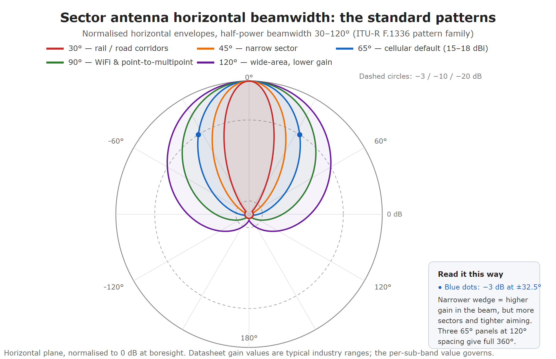
Four horizontal beamwidths cover almost every requirement:
30 to 45 degrees — rail and road corridors, elongated coverage, interference-limited areas. The highest gain of the sector types, but it requires precise azimuth alignment during installation.
65 degrees — the modern default for 3-sector cellular sites, typically around 15 to 18 dBi. Three units at 120 degree azimuth spacing give seamless coverage, with each neighbouring half-power point falling at the centre of the next pattern.
90 degrees — traditional 3-sector sites, outdoor WiFi access points, point-to-multipoint hubs. Slightly lower gain than 65 degrees but more overlap tolerance, which makes installation easier.
120 degrees — older site designs and wide-area, lower-gain requirements. Three sectors still give full coverage, with more inter-sector overlap than the narrower options.
The 65 degree pattern has become the default in cellular because of that interference geometry: at 120 degree azimuth spacing, the crossover between two sectors happens 60 degrees off each boresight, where both patterns are already 3 dB down. The 90 degree pattern survives wherever installation tolerance matters more than optimum interference geometry — outdoor WiFi hubs being the common case.
Sector versus omnidirectional
An omni antenna covers 360 degrees with low gain; a sector covers a slice with high gain. The choice follows directly:
Single point, all-around coverage, modest range — an omni is simpler: one antenna, one cable, no azimuth planning. Yard-scale WiFi, a small LoRa gateway or a vehicle-mounted unit are typical cases.
Coverage from the edge, or from a wall, or with range — a sector wins. A campus edge, a tunnel mouth, a stadium bowl, a corridor: all are wedges, not circles.
Multiple sectors on one structure — when capacity or range exceeds what one omni can deliver, three sectors at 120 degree spacing give roughly 5 dB more gain per direction than a comparable omni, plus the ability to tune each sector independently.
A useful special case is the combination approach: sectors arranged to synthesise full-circle coverage where an omni would be too weak. A 5 GHz MIMO sector antenna specified for 360 degree coverage arrangements exists for exactly this use.
Where sectorised antennas are used
Macro cellular sites
The classic three-sector configuration. Each sector faces outward 120 degrees from the next; each carries its own carriers; tilt is tuned per sector as the network matures. Modern deployments use multi-port MIMO panels — a 4G LTE MIMO sector antenna with plus and minus 45 degree cross polarization is the standard shape of this, and the plain single-polarity 90 degree outdoor LTE sector antenna remains common where capacity requirements are modest.
Rail and transport corridors
A corridor is the extreme case of elongated coverage: the serving area is a long, narrow wedge along the track. Narrow azimuth beamwidth of 30 to 45 degrees puts the energy along the line instead of across the countryside, raises effective range, and reduces interference to networks beyond the corridor. This is why rail and tunnel-portal specifications converge on narrow sectors.
Campus and outdoor WiFi
Point-to-multipoint WiFi from a rooftop or mast is a sector problem: the access point covers a defined wedge of the campus or neighbourhood, and neighbouring sectors on the same mast reuse the spectrum with spatial separation. Dual-polarity 90 degree units are the workhorses here, in both bands: a 2.4 GHz MIMO sector antenna with 90 degree dual polarity for range and penetration, and a 5 GHz MIMO sector antenna with the same 90 degree dual polarity where clean spectrum and capacity matter more than obstacle penetration.
Industrial and private networks
Mines, ports, plants and utility campuses need coverage along defined shapes — a pit wall, a quay, a production line — under dust and vibration. Sector antennas with customised radome and mounting options serve these; they also suit frequency bands outside the mainstream cellular ranges, such as 900 MHz MIMO base station sector antennas for private networks in rough terrain, where the lower band buys foliage and rock penetration that higher bands cannot.
Practical installation notes
Azimuth accuracy matters more as beamwidth narrows. A 120 degree pattern tolerates a 10 degree aiming error; a 30 degree corridor pattern does not. Use the horizontal pattern plot, not the mechanical bracket scale, to confirm boresight.
Tilt is set from the link budget, not by eye: the vertical beam should place the half-power points roughly at the inner and outer edges of the intended coverage area. Too little tilt leaks energy past the cell edge; too much creates a hole close to the site. Mechanical tilt physically leans the antenna and is adequate at small angles; electrical tilt shifts the phase of the array so the pattern points down without the radome moving, which keeps the horizontal pattern undistorted at high tilt angles and allows remote adjustment. The dedicated guide to remote electrical tilt (RET) antennas covers the mechanism and its trade-offs in detail.
Grounding and weatherproofing follow the same rules as any outdoor antenna, but one sector-specific detail is worth stating: because sector antennas are usually installed in groups on one structure, the wind load adds up. Verify that the pole, brackets and spacing are rated for the full group, not a single unit.
Frequently asked questions
Is a sectorised antenna the same as a sector antenna?
Yes. "Sectorised", "sectorized" and "sector" are three spellings of the same concept: a directional antenna covering a horizontal slice, typically 30 to 120 degrees. ITU-R documents use "sectoral".
Which beamwidth should I choose?
Start from the shape of the area to cover and the number of sectors available. Full-circle coverage from three positions points to 65 or 90 degrees; a corridor or interference-limited edge points to 30 to 45 degrees. If in doubt between two widths, the wider one is easier to install, the narrower one is easier to plan.
Is a sector antenna always better than an omni?
No. For a single point needing modest range in all directions, an omni is simpler and cheaper. Sectors win when the coverage area is wedge-shaped, when range or capacity exceeds an omni's gain, or when several sectors can share one structure.
Does higher gain mean longer range?
Higher gain concentrates energy, which extends range in the beam direction — but the same dB of gain comes from a narrower beam. The correct comparison is between the gain pattern and the required coverage shape, not between headline gain numbers.
Should I use mechanical or electrical downtilt?
Electrical tilt keeps the horizontal pattern undistorted at high tilt angles and allows remote adjustment, which is why it dominates in macro networks. Mechanical tilt is adequate at small angles and for fixed, rarely-adjusted installations such as corridor or campus links.
Can one sector antenna cover 360 degrees?
Not alone — but multiple sectors on one mast can. Three 120 degree units, or four 90 degree units, provide full-circle coverage with far more gain per direction than a single omni. Some models are specifically arranged for this purpose.
What else should a sector antenna specification state besides gain and beamwidth?
At minimum: the frequency sub-bands with return loss per sub-band, front-to-back ratio, cross-polarization discrimination for dual-polarity models, the tilt range and whether it is mechanical or electrical, and the wind load rating. For high-power or multi-carrier sites, add the PIM rating with its test power. A datasheet that omits most of these is a brochure, not a specification.
References
ITU-R Recommendation F.1336-5 (01/2019), Reference radiation patterns of omnidirectional, sectoral and other antennas for the fixed and mobile services for use in sharing studies in the frequency range from 400 MHz to about 70 GHz.
3GPP TS 38.104, NR; Base Station (BS) radio transmission and reception.
RF element manufactures sectorised antennas from 698 MHz to 5.8 GHz — from 900 MHz base station panels to dual-band WiFi sectors, including customised sector antennas for industrial networks and dual-band WiFi sector antennas. To match a beamwidth and gain to a coverage requirement, use the antenna selection tool.
TAG:What is a Sectorised Antenna https://www.rfelement.com