
5G MIMO Feedhorn for Parabolic and Grid Antenna
A dish antenna is only ever half a system. The reflector is a mirror, and a mirror decides nothing for itself: it re-radiates whatever the feed launches at it, in the pattern the feed hands over. Mount a poorly matched feed onto a 60 cm reflector and the measured gain lands several dB below the number printed on the dish, in a beam wider than the plot suggests. We build both halves of that pair — the feedhorns and the reflectors they sit in — so what follows is about the half that normally gets chosen last.
The half of the link the catalogue never shows
A feedhorn is a waveguide transition with a defined aperture and a defined phase centre. Its work is to illuminate the reflector evenly across the angles that matter, and then to stop, because radiation the dish sees beyond its own rim wraps around the edge and reappears in the sidelobes. That is why an 8 degree beam at the horn does not become an 8 degree beam in the sky. What decides the far-field result is focal geometry: how far the phase centre sits from the focus point, and how well the flare of the reflector matches the taper the horn provides. Three millimetres of focus error at that aperture costs more link budget than most project teams allow for in the whole design.
What our wideband feedhorn puts into a dish
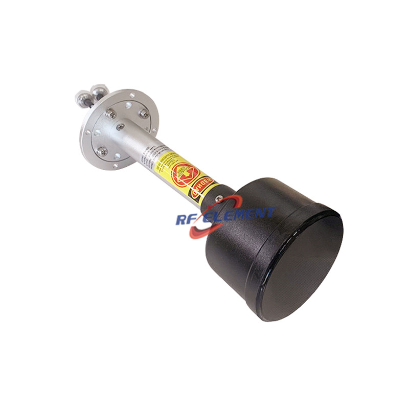
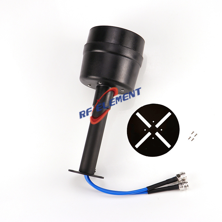
The 5G horn antenna we build covers 1700-4200 MHz continuously, with 1710-2700 MHz called out as a sub-range for the cellular bands beneath 2.7 GHz. Two ports leave the housing, one horizontal and one vertical, both N-type female; the interface is 50 ohm with a VSWR at or under 1.5, the figure that decides how much transmit power turns around at the connector instead of leaving through the aperture. Power handling is 50 W. The horn weighs 0.6 kg, which is not a minor detail: a light feed is a feed that keeps a dish pointed through the wind.
Gain belongs to the pair, not to the horn
We publish gain as two figures because one horn produces both. The same part delivers 25 dBi when it lights a 60 by 90 cm grid, and 23 dBi when that same feed faces a 60 cm solid reflector. Nothing inside the horn changed between those measurements; the aperture area did. This is the most common misunderstanding in the category. A buyer reads 25 dBi, bolts the feed onto a 45 cm reflector, and then reports that the product underperforms. The gain of a feed cannot be stated in isolation, and a supplier who quotes a single number is quoting the best dish that part has ever been tested in. Where a project wants the same platform for cellular use only, the 4G 5G MIMO feedhorn is the shorter ancestor of the wideband part, and the n78 feedhorn is what that platform becomes once the band is fixed.
A narrow band buys a tighter pattern
Commit a site to 3.5 GHz and the arithmetic changes. The n78 part works 3300-3800 MHz and reaches 23 dBi against a 60 cm reflector, holding an 8 degree pattern in both planes. Two things improve when the band narrows: the electrical size of the aperture grows relative to wavelength, so the beam tightens, and the match holds at 1.5 or better without the compromises a decade of bandwidth forces on the design. It weighs 0.8 kg, slightly heavier than the wideband horn, because the narrower design carries a different matching section inside the same black ABS and aluminium radome.
The mechanical decisions that decide whether the link survives
Every figure above is nullified by a mount that cannot hold angle. Our feedhorns are specified across minus 55 to plus 60 degrees Celsius, and that span is an engineering statement rather than a marketing one: it is the range over which the aluminium housing holds its dimensions and the 50 ohm interface does not drift. Pole mounting is the intended arrangement. The radome is black for a reason unrelated to appearance — a dark surface sheds ice faster than a white one on a north-facing pole, and ice across an aperture is a dielectric slab sitting in the signal path.
Grids on 2.4 GHz: the other half of this family
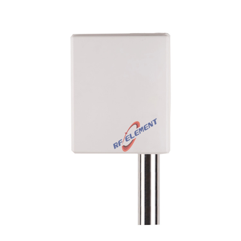
A grid does the same work as a solid reflector with less wind load and less mass, which is why 2.4 GHz backhaul hops are usually built on one. Our 2.4 GHz grid reflector works 2400-2500 MHz on linear polarization and delivers 15 dBi into a 16 by 21 degree pattern, with VSWR inside 1.5, 50 W of handling, one N-type female feed, and a 300 by 400 mm aluminium reflecting surface at 1.2 kg. When a hop needs more margin, the 600 by 900 mm grid tightens the beam to 12 degrees by 15 degrees and relaxes the match to 1.8, at 3.2 kg and still capped at 50 W with one N-type female connector.
When the hop moves above 4.9 GHz
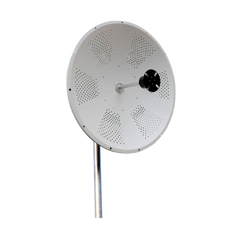
Higher up the spectrum the reflector becomes the whole antenna and the feed disappears inside it. The 60 cm parabolic dish spans 4900-6000 MHz with dual linear polarization, keeps its front-to-back ratio at 32 dB or better and cross-polar isolation at 30 dB or better, handles 100 W over two N-type female feeds, and mounts a 600 mm aluminium reflector weighing 7 kg. The 90 cm version raises front-to-back to 35 dB or better on a 900 mm aperture at 12 kg. Which hop interferes with its neighbour is normally decided by those two isolation figures rather than by gain.
Why a bigger reflector is not automatically the upgrade
It is tempting to treat aperture diameter as a volume knob. Two forces push back. Wind load grows with the square of the diameter, and the mount has to carry not only the mass but the moment the reflector applies to the pole, which is why a 900 mm aperture at 12 kg is a different structural problem from a 600 mm at 7 kg; a pole that deflects under gust is a link that fades on windy afternoons. The second force is aiming tolerance. A 4 degree beam has to be pointed roughly twice as accurately as an 8 degree beam to hold the same loss, which means the mount must stay rigid through a season of thermal cycling. Ordering the larger reflector without ordering the larger mount is how a link ends up performing worse than it did before.
Where the wrong choice shows up
The first mistake is a feed chosen for gain and installed in the wrong reflector: a wideband horn specified at 25 dBi, mounted on a 45 cm dish that can hold only 21, and then judged against the number the first dish produced. The second is a grid aimed at a target the site cannot see — 2.4 GHz needs line of sight, and a hop through a treeline loses more to foliage than any amount of reflector area gives back. The third is polarization treated as an afterthought, when a dual-polarized pair is the entire reason a MIMO hop carries two streams rather than one. Each of these is settled before a single bracket is ordered.
What we need to quote a feed
Start with the band plan, the reflector size and style, the distance you need to close, and whether the hop carries one stream or two. We come back with a named feed, its specification sheet, a mounting drawing, and a short note on the focus or isolation points your geometry puts at risk. Tooling on a new reflector starts from a drawing you approve, and we are happy to begin with a single unit so a pilot link can be measured before anyone commits to volume. Email sales@rfelement.com and treat the figures in your link budget as the acceptance test the delivered hardware has to pass.
TAG:5G MIMO Feedhorn for Parabolic and Grid Antenna https://www.rfelement.com