RF element,Update The Microwave Anechoic Chamber
An antenna datasheet is only as honest as the room it was measured in. Every gain figure, beamwidth, and isolation number we publish comes out of a microwave anechoic chamber — a room lined with pyramidal absorber foam that swallows reflections instead of bouncing them back, so the only signal the measurement horn sees is the one that traveled the direct path. This update covers what changed in our test setup and how the numbers reach your datasheet.
Why reflections ruin antenna measurements
Measure an antenna in a normal room and the walls return copies of the signal milliseconds-free but meters late; they add and subtract from the direct wave, and the pattern analyzer records a rigged result — ripples in the gain curve, false lobes, a beamwidth that depends on where the furniture is. Absorber foam converts those reflections into heat, and the chamber behaves, electrically, like free space. That is the entire point of the room: it lets us measure what the antenna does, not what the building does to it.
What the upgraded chamber covers
Our upgraded microwave anechoic chamber spans 300 MHz to 8.5 GHz with a 32-probe system. The probe array matters as much as the frequency range: instead of rotating a single measurement horn through every angle and waiting, the array samples the radiation pattern from many directions at once, which shortens each sweep and lets engineers run more design iterations per day. For sub-6 GHz 5G work — 698-4200 MHz antennas with patterns that must hold across six sub-bands, as the 3.5 GHz n78 panel does across its own — that iteration speed is what turns a spec change into a verified result within a working week.
What we measure in the room
Each new design passes through the same checklist:
Radiation pattern — the full 3D cut, from which peak direction and sidelobe levels are read.
Gain by sub-band — measured against a reference standard, not simulated, per the sub-band table on the datasheet.
Beamwidth — horizontal and vertical, at the −3 dB points.
Port isolation — on MIMO models, how much of one port's signal leaks into the other.
VSWR — measured at the connector with the antenna in free-space conditions; our tables publish per-model ceilings from 1.5 on the n78 panel to 1.8 on the wideband omni.
Passive intermodulation runs on separate bench equipment with the carrier power set to match the datasheet condition — 2×20 W for the 5G cellular models, 2×43 dBm for the industrial ones — but the same free-space discipline from the chamber governs the fixture.
A worked example: the 7 GHz microwave dish
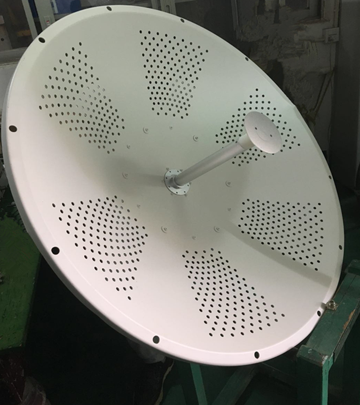
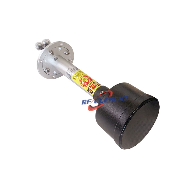
Our 7 GHz microwave MIMO parabolic dish shows the loop end to end. The requirement was dual-polarized operation across 6400-7200 MHz with gain above 32 dBi, which pointed to a 90 cm reflector and a custom dual-polarized feed — the feed being the hard part at those frequencies. After the first simulation pass, the feed went into the anechoic chamber for pattern, gain, and beamwidth measurement; the results drove iterative feed adjustments until the antenna met the specification. The published result: 32 dBi gain with the 90 cm reflector, VSWR below 1.8, both polarizations live across the full 6400-7200 MHz band, the feed alone weighing 0.8 kg. No number in that table exists outside the chamber.
From sweep to specification table
The path from a sweep to the sub-band table is deliberately boring. A model enters the chamber with a provisional design; the probe array records the pattern; gain is read per sub-band against a reference antenna; beamwidth and isolation are extracted from the same dataset. What lands on the datasheet is the measured row, not the simulation that predicted it. Take the wideband MIMO ceiling model: its datasheet climbs from 1.5 dBi in the lowest sub-band to 5.5 dBi at the top of the band, with port isolation tightening to 22 dB in the C-band, all inside a 280 × 15 mm radome — every cell in that ladder is a chamber reading, and the compact single-port sibling carries its own −153 dBc figure from the intermodulation bench rather than a scaled copy; the n78 feedhorn's 23 dBi on a 60 cm dish and the outdoor panel's 10-25 dB isolation span were read out of the same dataset. The same rule applies at the top of the range: the 2-port low PIM MIMO panel publishes −153 dBc at 2×43 dBm across 698-3800 MHz in a 360 × 155 × 65 mm, 1.1 kg enclosure, and nothing in that row was extrapolated.
Reading chamber numbers against real deployments
The chamber's job is to remove the environment; a deployment's job is to live in one. Our 13 GHz microwave panel is rated at 28-30 dBi with a 5° × 3.5° beam and IP65 sealing — chamber figures that a customer then confirms on a live microwave hop. When the two disagree, the chamber data is the arbiter: it separates the antenna's own behavior from the tower, the cable run, and the weather. That is why we recommend keeping the datasheet's chamber-measured figures as the acceptance baseline in tenders, and treating field sweeps as a commissioning record rather than a redefinition of the product.
Verified figures now live in the catalog
A short tour of what the chamber has already signed off: the 4-port slim ceiling at 385 × 13 mm holds −153 dBc while keeping four ports within a 13 mm radome; the cross-polarized outdoor panel pairs 8 dBi of mid-band gain with isolation that climbs from 10 dB to 25 dB as frequency rises; the 11 dBi fiberglass omni keeps an 8° vertical beam over its 630 mm length; and the dual-polarized 90 cm dish at 34 dBi for 5 GHz links came out of the same room as the 30 dBi 60 cm version. Below 5 GHz, the low PIM MIMO panel holds −153 dBc at 2×43 dBm with VSWR at or under 1.8 across all three of its sub-bands. Each of those rows exists because the chamber said so, and the datasheet repeats what the room reported.
Where chamber-only claims are the wrong benchmark
A chamber verifies the electrical design; it does not certify mechanical survival. Wind load, radome UV life, and connector torque over storm seasons are validation items with their own test rigs, and we state them separately rather than folding them into the RF tables. If a supplier quotes you a single "tested" figure without saying which test it came from, ask which room the antenna was in — and what else was in the room with it.
Ordering, samples, and what we send you
Every model in the catalog ships with its chamber-measured electrical table; custom variants get the same sweep before the sample leaves ZhaoQing. Sample units are on the road within a week of an approved drawing, production runs to a scheduled factory calendar quoted per order, and MOQ leaves room for a pilot site. Email sales@rfelement.com with the frequency plan and link budget, and the reply carries the model match, the measured specification table, and a note on which chamber setup produced each figure — your tender and our test bench then quote the same numbers, from the same room.
TAG:RF element,Update The Microwave Anechoic Chamber https://www.rfelement.com