
VHF Omni Antenna | High Performance VHF Antenna | 144-174MHz
Specifications
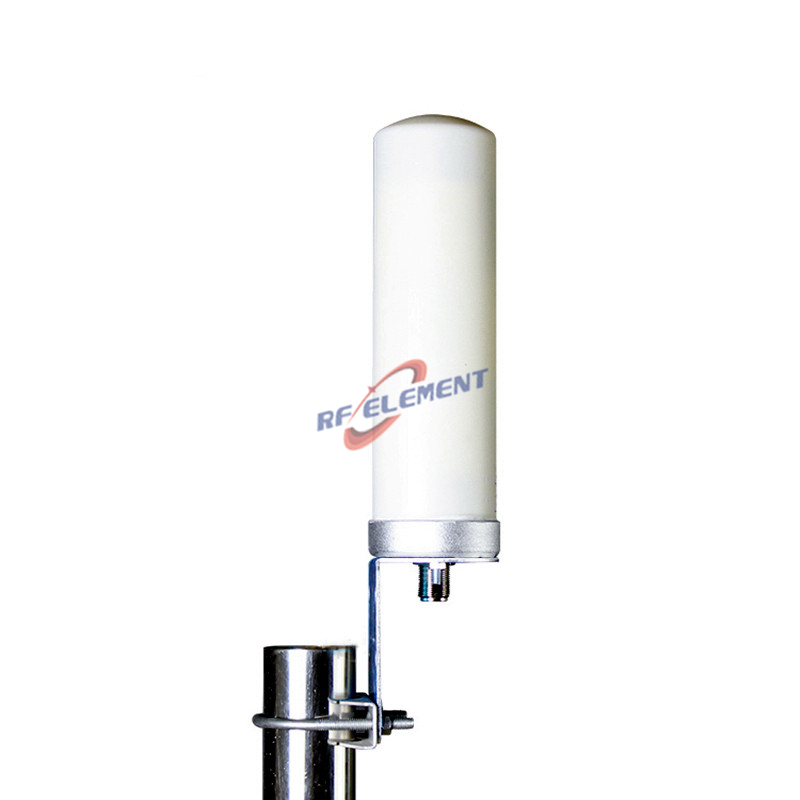
A VHF omni antenna for 144 to 174 MHz is a 1.54 m fibreglass rod with 3 dBi, and at that frequency a single decibel of gain costs far more money and mast space than it does at 5 GHz. The useful question is therefore not how to get more gain but where the height and the clearance come from, because at 150 MHz the first Fresnel zone is tens of metres wide and the ground reflection is what actually decides the coverage edge. This page covers the length against wavelength, the height gain that beats antenna gain, the matching that produces a 1.21 to 1 band, and the mast details that change the pattern.
1540 mm is three quarters of a wavelength at 144 MHz
At 144 MHz the free space wavelength is 2.08 m, so the 1.54 m radome is 0.74 wavelengths long. At 174 MHz, where the wavelength falls to 1.72 m, the same rod is 0.89 wavelengths. That is the physical reason the gain is 3 dBi: a half wave dipole in free space gives 2.15 dBi, and this antenna adds about 0.85 dB on top of that by extending the radiating length and using the mast as part of the system.
The 41253 rule checks the figure from the other side. Dividing 41253 by the product of 360 degrees horizontal and 50 degrees vertical gives 2.29 in linear terms, or 3.6 dBi. The datasheet says 3 dBi, so the aperture efficiency is about 87 percent, which is a normal figure for a collinear rod inside a fibreglass tube. When a supplier quotes 6 dBi from the same 1.5 m length, either the vertical beam is narrower than 50 degrees or the number has been rounded upwards, and the two beamwidths in the table are enough to tell which.
At VHF, mast height beats antenna gain
Over flat ground the received field at low angles is the sum of a direct ray and a ground reflected ray, and the two add constructively as height rises. Doubling the height of the antenna above ground can add up to 6 dB at the horizon. Raising a mast from 10 m to 13 m adds about 2.3 dB, which is more than the difference between this 3 dBi antenna and a 5 dBi antenna of twice the length and twice the wind load. The money is better spent on the mast than on the gain.
Obstruction is the other half of the same argument. At 150 MHz the first Fresnel zone radius at 5 km, mid path, is about 50 m, which is large compared with the radius at 5 GHz. A building, a treeline or a ridge that looks clear on a map can still cut into that zone and cost more than any antenna change. On VHF the path profile is the design, and the antenna is the last few decibels at the end of it.
| Frequency Range | 144-174MHz | |
| Polarization | Vertical | |
| Gain(dBi) | 3 | |
| Horizontal Beamwidth | 360° | |
| Vertical Beamwidth | 50° | |
| Impedance | 50Ω | |
| VSWR | ≤ 1.8 | |
| Maximum Power | 50W | |
| Connector Type | 1 Port, SMA-Type/ N-Type | |
| Antenna Dimension(mm) | Φ 25*1540 | |
| Net Weight | 1.2 kg | |
| Operating Temperature | -55° to +60° C (-67° to +140° F) | |
| Radome Material | Fiberglass | |
| Radome Color | White/Grey | |
| Mounting Options | Pole Mounting | |
Where the 1.21 to 1 bandwidth comes from
The band runs from 144 to 174 MHz, a ratio of 1.21 to 1, which a thin 25 mm rod cannot hold on its own. The bandwidth is produced by a matching network in the base, and that network is the reason the VSWR stays at or below 1.8 across the whole range. A VSWR of 1.8 is a reflection coefficient of 0.286, a return loss of 10.9 dB and a mismatch loss of 0.37 dB, so the price of covering the full band in one part is under half a decibel.
There is a trade inside that number. Widening the match costs efficiency, because the loading coil and the matching section dissipate some of the power that would otherwise radiate. A narrower band version of the same rod can show slightly more gain for the same length. Where the deployment uses only 144 to 148 MHz or only 162 to 174 MHz, a band specific part is worth asking about; where the radio may be reprogrammed across the band, the wide version is the safer purchase.
The mast is part of the antenna
A side mounted rod couples to a metal mast, and at 150 MHz the mast is a significant fraction of a wavelength in diameter. That coupling skews the pattern away from the mast and shifts the match, which is why the mounting instructions matter more here than on a 5 GHz panel. A standoff of 0.3 to 0.5 m between the rod and the mast keeps the coupling small; mounting at the top of the mast, above the structure, removes it almost entirely.
The mechanical numbers are modest. The antenna weighs 1.2 kg and presents about 0.039 square metres of frontal area, which is roughly 38 newtons at 40 metres per second. The load is not the problem; the length is. A 1.54 m rod on a short bracket acts as a lever, so the bracket has to be clamped to the mast rather than to a thin wall, and the coax should leave the base with a drip loop so that water runs away from the connector instead of into it.
Power, connectors and the 50 degree vertical beam
The power rating is 50 W, which covers the 25 to 50 W base stations this band is usually built around. The connector is offered as SMA type or N-Type. Outdoors, the N-Type is the better choice: it is larger, it seals better and it has lower loss, while the SMA is adequate for a short indoor run or a receiver only installation. Whichever is chosen, the joint should be taped with self amalgamating tape, not silicone.
The vertical beam is 50 degrees, so with the pattern centre at the horizon the lower edge is 25 degrees below it. From a 20 m mast that edge reaches the ground at about 43 m, and beyond that distance the ground is served by the low angle part of the pattern, which is exactly where the height gain described above pays off. The specification does not state whether the antenna is DC grounded, so a coaxial surge arrestor and a separate ground kit should be part of the installation rather than an assumption about the radome.
Where the deployment moves into the UHF business band, the 450 MHz antenna category page covers the 450 to 470 MHz alternatives. The full catalogue, including this rod, is on the RF product range page, and the antenna selector tool filters by band, gain and mounting style.
Send the mast height, the terrain profile and the radio model to sales@rfelement.com, and we will confirm whether the 3 dBi rod is the right choice or whether a taller mast is the cheaper route to the same coverage.
FAQ — VHF Omni Antenna
What is the VHF Omni Antenna used for?
What frequency band does the VHF Omni Antenna cover?
What are the key specifications of the VHF Omni Antenna?
Can RF element customize the VHF Omni Antenna for my application?
What is the MOQ and lead time for the VHF Omni Antenna?
How do I get a quotation for the VHF Omni Antenna?