Dual Band Sector Antenna: 2.4/5.8 GHz Selection Guide
Two bands, one radome, one mounting point. That is what a dual band sector antenna promises, and it hides a decision most projects take too late: the 2.4 GHz pattern and the 5.8 GHz pattern leaving the same aperture are not the same shape. On the widest part in our range the horizontal beam holds at 62 degrees on 2.4 GHz and narrows to 58 degrees up at 5.8 GHz, while the vertical beam falls from 14 degrees to 8. Size the sector count from the narrow figure, or the outer cells develop gaps that no link budget was written to cover.
Sector or omni: the trade written in degrees
An omni spends its power around a full circle. A sector antenna aims the same watts into a slice of that circle, and the arithmetic rewards a perimeter. Narrowing a full turn to a 90 degree cell concentrates the power into a quarter of the azimuth, which is worth about 6 dB of directivity before a millimetre is added to the aperture. That is the whole case for sectors on a fenced site, a mine gallery, or a WISP corridor: not more power, the same power aimed where traffic lives. Where a site is harsh as well as wide — a coal face, a tunnel network — the same idea is built on a rugged dual band sector sealed to IP67 and specified down to -40 °C.
Two patterns inside one radome
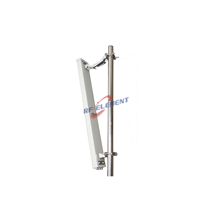
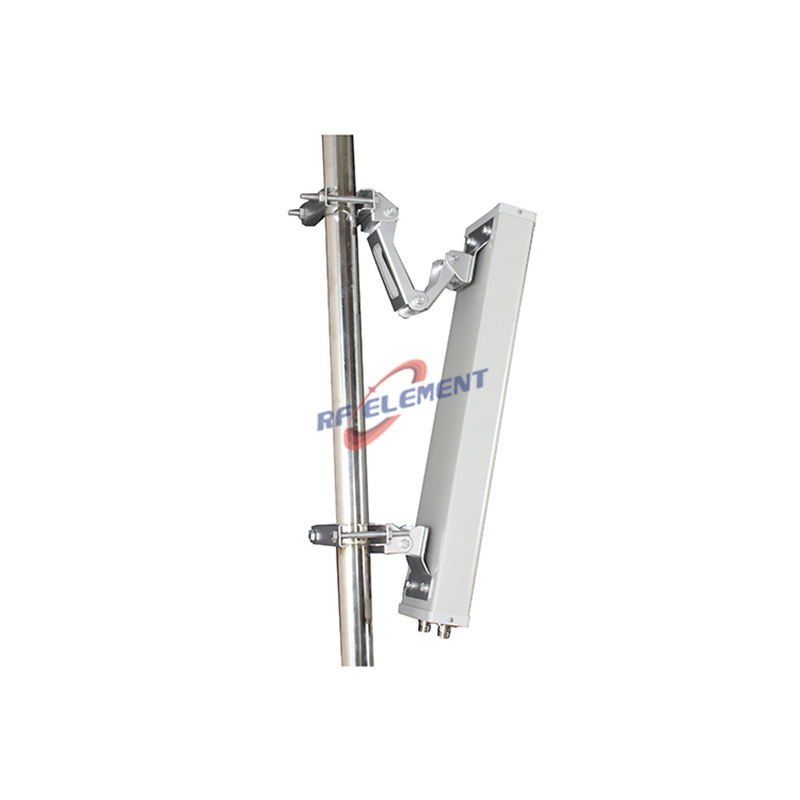
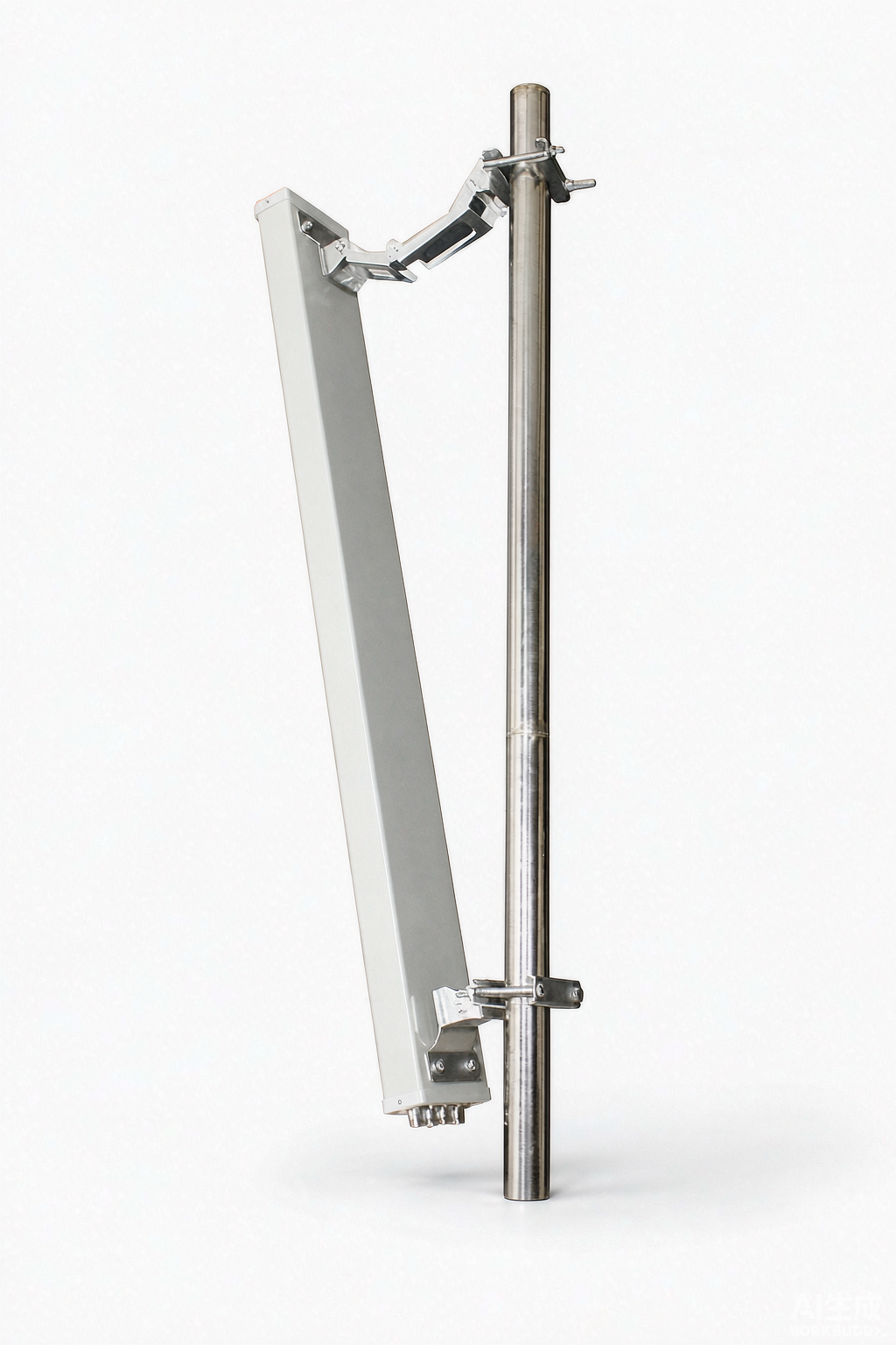
The 2.4 GHz figure on a dual band sector is nearly always the lower of the two, and that is aperture physics rather than a manufacturing weakness: gain scales with electrical size, so one reflector does more work at the higher frequency. We publish the horizontal beam as a pair of values, 65 and 90 degrees, because the low and high bands do not share a pattern, and the vertical beam follows the same rule, 15 degrees at the bottom of the range against 7 at the top. The radiator sits inside a PVC housing a little under a metre long, 128 mm tall and 58 mm deep, weighing 3.5 kg, fed through a four-port N-type female interface rated for 100 W of continuous power.
Plan coverage on the narrow band and treat the wide one as margin. A deployment sized on the 2.4 GHz beam will under-cover at 5.8 GHz by a margin that widens with distance, and the symptom is a client that associates happily and then drops back to the lower band.
Choosing the horizontal beam: 65, 90 or 120 degrees
Three numbers cover almost every site. A 90 degree cell is the default because four of them tile a circle with the least overlap. A 65 degree cell buys extra gain in the same body length, which is the right call when the mast is already crowded and a second sector position is not available. A 120 degree cell cuts the sector count to three and the cabling to three runs, at the cost of a wider beam that spends energy on ground the site does not own. Where the surrounding network still runs on 4G, the 698-2700 MHz sector covers the low bands and the mid band from one panel.
The decision is usually mechanical before it is electrical. Every extra cell on a mast means another mount, another jumper, another wind-loaded panel, and another set of readings at commissioning. Sites that start with six narrow cells frequently finish with four wider ones once the mount budget is counted.
Four 90 degree cells making a full circle
A US integrator came to us for a 5.8 GHz WiFi ring built from four 90 degree cells rather than a single omni. The requirement was a cell rated above 15 dBi with a horizontal beam held at 90 degrees, polarisation of ±45 degrees to keep four transmitters on one mast from talking over one another, and a VSWR inside 1.8 so the four-way splitting network stayed predictable.
Holding a 90 degree edge at that gain is a reflector problem rather than an amplifier problem. The pattern out of a sector is set by the shape and size of the aluminium plate behind the radiator, so the work went into reshaping that plate until the beam cut off where the drawing said it would. Four cells at 90 degrees then cover the circle with the fewest overlaps, and each one can be tilted or re-aimed without disturbing its neighbours.
Polarisation discipline is what makes four transmitters cooperate. With every cell set the same way, the boundary between two of them carries two signals at equal strength and no way to separate them. Rotating the polarisation of alternate cells turns that boundary from a source of interference into a source of isolation.
Gain, length and wind load
Gain is bought with aperture, and aperture on a sector means length. The range shows it plainly: a 5 GHz part at 19 dBi needs a 770 mm by 115 mm by 60 mm body, the dual band part at 16 dBi needs 980 mm of length, and the single-band 2.4 GHz and 5 GHz parts at 14 and 15 dBi fit into 510 mm by 128 mm by 58 mm at 3.0 kg each. All three are rated for 100 W.
What that means in practice turns on the clamp rather than the radio. A longer body on the same bracket presents more area to the wind and more bending moment at the fixing, and the pattern only stays where it was aimed if the clamp holds angle through a year of hot days and cold nights. A higher-gain part on an unreviewed clamp will finish below its datasheet.
When a sector is the wrong tool
A room does not need a sector. Indoors the ceiling sits within a few wavelengths, reflections dominate, and a focused beam aimed horizontally will cover the far wall and miss the floor. Take the ceiling part and more access points instead.
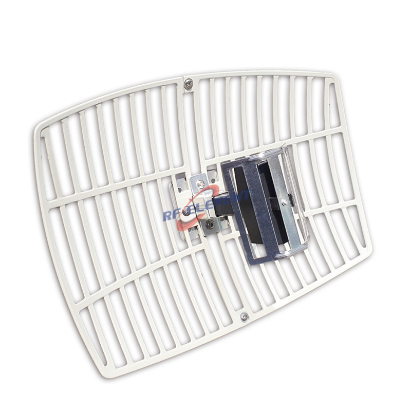
A single point-to-point hop does not need a sector either. A sector spreads its energy across an arc; a parabolic grid or dish puts all of it on one bearing, and for one distant endpoint that is strictly better.
And a site whose traffic is genuinely everywhere — a square, a stadium concourse, a market — will not be fixed by narrower and narrower sectors. Past about six cells, the overlaps and the cabling start eating the gain the extra cells were meant to buy.
Environment, mounting and the part that decides the outcome
Two ratings carry most of the weight outdoors. A specified operating window describes the span in which the aluminium body keeps its shape and the feed point stays on frequency; it is an engineering statement, not a marketing one. So does the relationship between the two bands: a part quoted down to -55 °C and up to +60 °C has been tested across both, not at room temperature with a note attached. The second is the shell. A PVC radome, sealed properly at the base, keeps water out of the feed, and water in a feed is the one failure that no amount of gain compensates for.
Pole mounting is assumed across this family, and the two figures worth confirming before the order ships are the mast diameter and the cable run. A jumper that is too short forces the bracket onto a position the coverage plan did not want, and a radome colour that clashes with a landlord's rooftop is the sort of detail that delays an acceptance by weeks. It also pays to have the mechanical drawing signed off by the building owner before anything is ordered.
Briefing a sector deployment
Say which bands have to share one aperture, the horizontal beam you have chosen, the sector count and the radius each cell has to hold, the mount type and mast diameter, and the port count your radio expects. We name the part, attach its drawing, and flag the pattern, isolation or mount risk your geometry creates.
If the standard part is close but not exact, changing the connector, the cable length, the bracket or the radome colour is routine OEM/ODM work, and gain or beamwidth can be retuned per band where the application justifies it. First articles leave the line inside a working week of drawing approval, and volume scheduling is quoted against the volumes you confirm; the smallest production run is sized so a pilot site can be instrumented before a rollout is committed. Send the coverage plan to sales@rfelement.com; the beamwidth in it is the beamwidth the delivered part will be measured against.
TAG:Dual Band Sector Antenna: 2.4/5.8 GHz Selection Guide https://www.rfelement.com