Yagi vs Grid vs Panel: How to Choose Directional Antenna Gain
Yagi vs Grid vs Panel: How to Choose Directional Antenna Gain
Two directional antennas, both labelled 15 dBi, can behave nothing alike. One spreads its energy across a 33° cone. The other squeezes it into an angle roughly half that wide, weighs nearly three times as much, and asks for a mast that will not twist in a gust. The gain figure on the label is identical. The link you get is not.
That is the part most buying guides leave out. Gain is not amplification — it is concentration. An antenna takes the power you feed it and presses it into a narrower solid angle, and every decision about that angle is paid for somewhere else: in bandwidth, in weight, in wind load, or in how precisely you have to aim. This guide compares the three directional structures we manufacture — Yagi, parabolic grid and panel — across the 10 dBi to 22 dBi range, using published beamwidth and mechanical data from our own product line.
Gain is concentration, not amplification
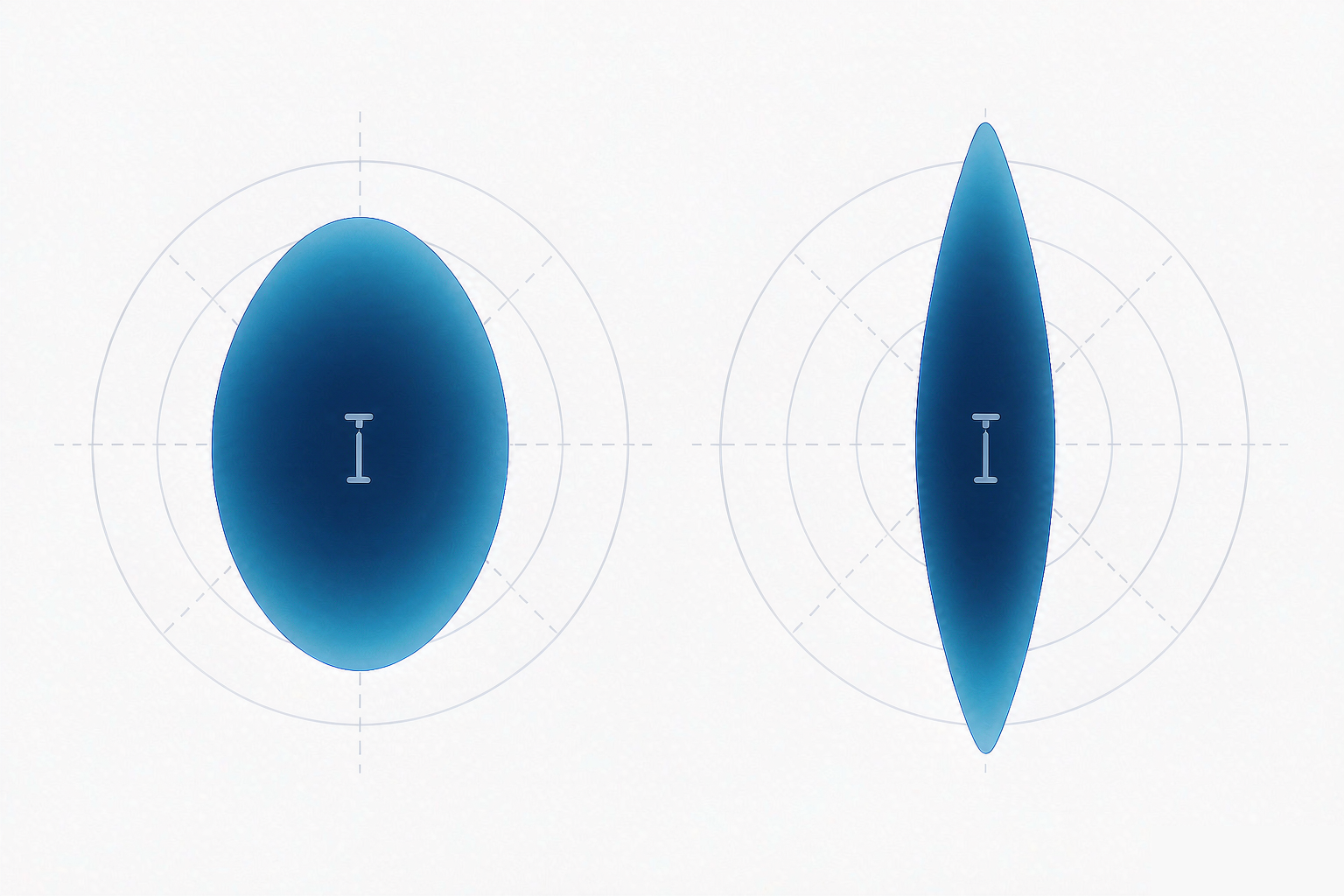
dBi expresses an antenna's forward intensity relative to a theoretical isotropic radiator that spreads energy equally in all directions. A 10 dBi antenna is not "ten times stronger" in any useful sense; it delivers roughly ten times the on-axis power density of that reference, by putting correspondingly less energy everywhere else. Every 3 dB of additional gain doubles the on-axis power density — and roughly halves the solid angle over which that density is delivered.
That conservation is what makes antenna selection a trade-off rather than a ranking. There is no better gain figure in the abstract, only a gain figure that matches the cone your link actually needs. The practical measure of that cone is the half-power beamwidth: the angular width within which radiated power stays within 3 dB of the peak. Once you know the horizontal and vertical beamwidth of a candidate, you know two things at once — how far it will reach for a given input power, and how much of your aiming tolerance it will consume.
The beamwidth trade-off, in our own numbers
Our vertical Yagi family uses the same basic structure across adjacent bands, which makes the trade-off easy to see:
| Model | Band | Gain | H × V beamwidth | Length × weight |
|---|---|---|---|---|
| UHF Yagi | 450–470 MHz | 10 dBi | 65° × 60° | 815 × 370 mm · 0.8 kg |
| GSM Yagi | 824–960 MHz | 12 dBi | 55° × 50° | 800 × 185 mm · 0.6 kg |
| 900 MHz Yagi | 824–960 MHz | 14 dBi | 40° × 35° | 1350 × 185 mm · 1.1 kg |
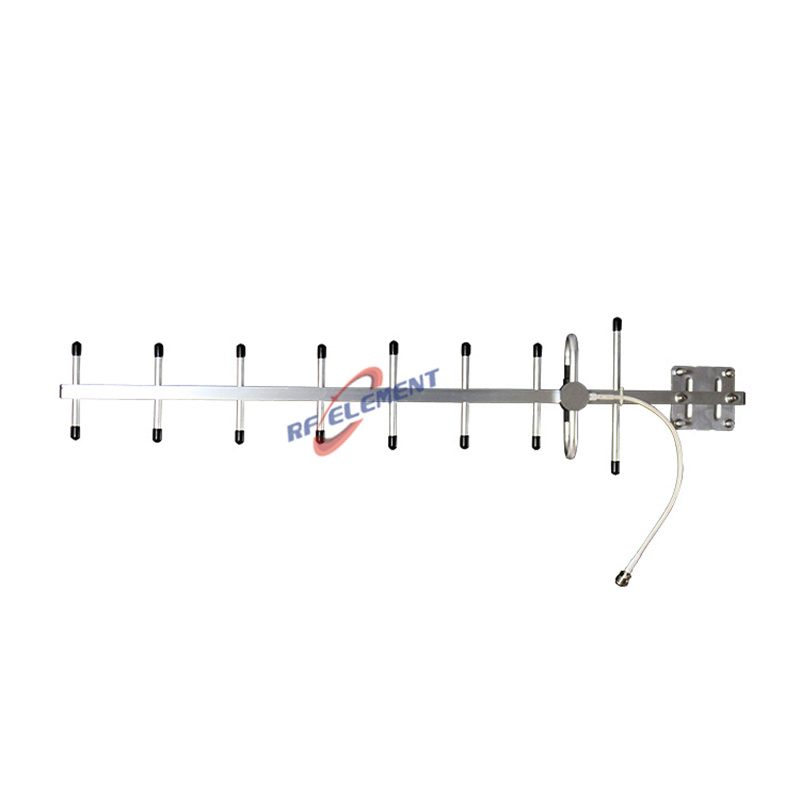
| 2.4 GHz WiFi Yagi | 2400–2500 MHz | 15 dBi | 33° × 30° | Φ75 × 505 mm · 1.5 kg |
Read that table within a single band and the trade-off is unambiguous. On 824–960 MHz, one step of 2 dB — from 12 dBi to 14 dBi — narrows the pattern from 55° × 50° to 40° × 35°, lengthens the boom from 800 mm to 1350 mm, and nearly doubles the weight. The extra gain did not come from nowhere. Because the rows above span several bands, their beamwidth figures are not directly comparable from one line to the next: settle the band you need first, then compare within it.
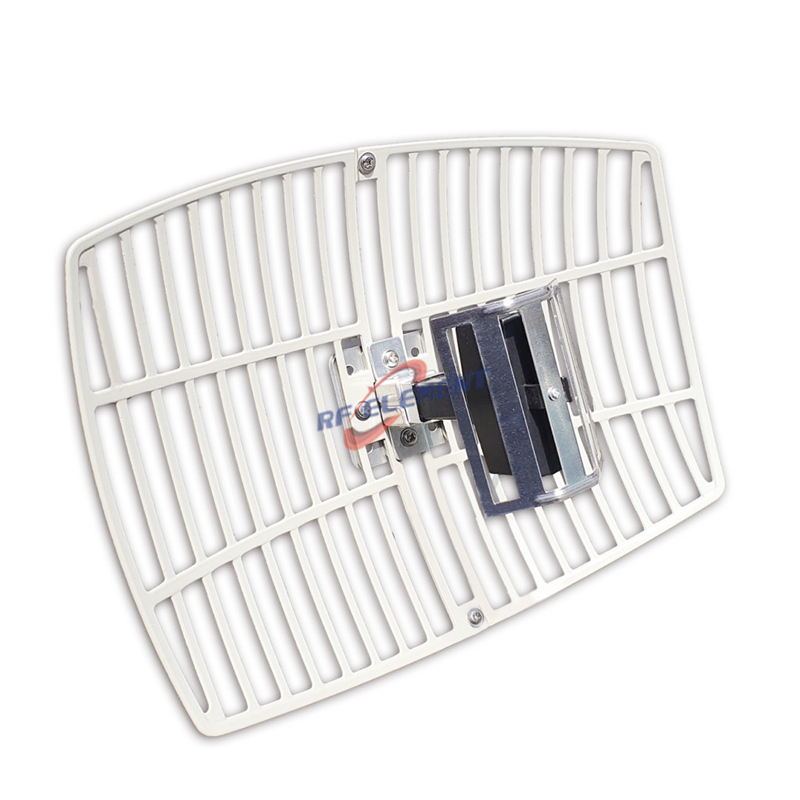
The same arithmetic governs the higher-gain end. Our two dual-band parabolic grids cover 2400–2500 MHz and 5150–5850 MHz through one reflector; the 15/16 dBi model measures 300 × 400 mm and weighs 1.2 kg, while the 21/22 dBi model grows to 600 × 900 mm and 3.2 kg. More than four times the reflector area buys 6 dB, and a beam of 12° × 15°. Whether that is worth a heavier mast — and a stiffer one — is a site decision, not a specification decision.
One caution about comparing across structures. Published beamwidth figures belong to the band and configuration the manufacturer measured them in, and dual-band products can quote the narrower high-band figure alongside the low-band gain. Before you compare two antennas, confirm the beamwidth is quoted for the frequency you will actually use.
Three structures, three sets of compromises
Yagi — the lightest way to get directional
A driven element, a reflector and a row of directors. The Yagi reaches useful directivity with the least material, which is why it remains the default for cost-sensitive and weight-sensitive links.
Strengths: lowest weight and wind load per dBi; simple pole mounting; predictable, well-understood pattern.
Limits: narrow relative bandwidth — roughly 4% on our 450–470 MHz model and about 15% across 824–960 MHz. Additional gain comes from lengthening the boom rather than enlarging an aperture.
Our range: 10 dBi UHF, 12 dBi GSM, 14 dBi 900 MHz, an 11 dBi ±45° dual-polarised 900 MHz model for MIMO and polarisation-tolerant links, and a 15 dBi 2.4 GHz WiFi Yagi with a weatherproof radome.
Parabolic grid — the efficient path to 20 dBi
A curved grid reflector with a feed at the focus. Aperture efficiency is high, and because the reflector is frequency-scaled rather than tuned, one dish can serve two widely separated bands.
Strengths: highest gain in our catalogue; dual-band coverage from a single feed; comparatively low sidelobes for its gain.
Limits: wind load and mass rise with area, and the beam becomes unforgiving — at 21/22 dBi the pattern is 12° × 15°, so a mast that moves a few degrees moves the link off peak.
Our range: 15/16 dBi and 21/22 dBi dual-band WiFi grids. For background on where they earn their keep, see the advantages of dual band WiFi parabolic grid antennas.
Panel — the flattest, most installable option
A printed array behind a flat radome. The panel gives up some of the grid's peak gain in exchange for a low profile, low wind load and a mounting job that one person can finish.
Strengths: flat form factor (our 18 dBi model is 305 × 305 × 25 mm); wide bandwidth; easiest alignment because the radiating face is obvious and stable.
Limits: gain tops out below a comparable grid; the horizontal and vertical patterns are not identical, so elevation and azimuth tolerances differ.
Our range: 14 dBi (35° × 30°, 0.9 kg) and 18 dBi (22° × 20°, 2.0 kg) 2.4 GHz models.
Choose by constraint, then by gain
The order in which you evaluate candidates matters more than the candidates themselves. Working outward from the site:
Line of sight and Fresnel clearance first. No gain figure rescues a link with an obstructed first Fresnel zone. This is decided by height and path, not by the antenna.
How much angular tolerance you need. Covering one fixed tower on a rigid mast tolerates a narrow beam. Covering several endpoints, or a mast that sways, does not. This single question usually narrows the beamwidth you can accept.
Bandwidth. A single band and a fixed channel suit a Yagi. Two bands, or a future band change, point to a grid or panel.
Mechanical limits. Wind load, mast strength, cable routing, appearance constraints. A 600 × 900 mm reflector is a structural decision as much as an RF one.
Gain figure last. Once the four constraints above are fixed, the gain you can use is mostly determined — and it is often lower than the number you first wanted.
A sanity check worth doing. Free-space path loss in dB follows 32.44 + 20·log₁₀(f in MHz) + 20·log₁₀(d in km). At 2.4 GHz over 5 km that is 114.0 dB. Subtract that from transmit power plus both antenna gains, less feeder and connector losses, and compare the result with your receiver's sensitivity. If you are working with 3 dB of margin, removing 3 dB of cable loss is worth exactly as much as doubling the antenna gain — and usually costs less.
Four things that quietly eat your gain
1. Feeder loss
Every 1 dB of cable loss throws away about 20.6% of the power you put into it, and the loss grows with both length and frequency: the same cable run attenuates far more at 5.8 GHz than at 450 MHz. A high-gain antenna at the top of a tall mast fed by a long, thin coax is one of the most common self-inflicted failures in outdoor links — the gain you paid for can disappear entirely in the run. Size the cable to the band and the distance, and keep the run as short as the site allows.
2. Polarisation mismatch
A linear antenna receiving a linear signal loses 20·log₁₀(cos θ) when the polarisation planes are rotated by θ from each other: about 3 dB at 45°, and effectively nothing received when they are orthogonal. Where polarisation is uncertain, or where MIMO operation is intended, a dual-polarised design removes the guesswork — our ±45° 11 dBi 900 MHz Yagi exists for exactly that reason.
3. Aiming tolerance and mast stability
A 12° beam leaves little room for movement: a few degrees of mast twist or sag moves the link materially off peak. A 65° beam absorbs the same movement without noticing. The narrower your beam, the more the mast becomes part of the RF design — including its guy wires and its foundation.
4. Sidelobes and interference
A narrow main lobe does not guarantee a clean pattern. In co-located or urban sites, energy collected through sidelobes arrives as interference, and the symptom is a link that reports strong signal and poor throughput. Reflector-based designs generally hold their sidelobes lower than comparably sized Yagis, which is one reason grids are common in dense spectrum environments.
When a directional antenna is the wrong answer
If your endpoints are mobile, or spread around the horizon, directivity works against you: you need coverage angle rather than reach. Omni and sector antennas exist for that case, and the trade-offs run in the opposite direction — lower gain, wider pattern, more of the site covered. We compare those structures separately for WiFi and cellular sector deployments, and our 2.4 GHz range covers both.
Frequently asked questions
Which has more gain — a Yagi or a parabolic grid?
Neither is inherently better; the aperture sets the ceiling. A Yagi adds gain by lengthening its boom (our 14 dBi model is already 1350 mm), while a grid adds gain by enlarging its reflector (our 22 dBi model is 600 × 900 mm). In our catalogue that places Yagis at 10–15 dBi and grids at 15–22 dBi, with grids carrying the high-gain end because a reflector can reach a very narrow beam within an acceptable weight.
How much gain do I need for a 5 km line-of-sight link?
Distance alone does not set the answer. Compute free-space loss first, subtract it plus feeder losses from transmit power plus both antenna gains, and compare the result against receiver sensitivity. At 2.4 GHz over 5 km, free-space loss is 114.0 dB. In practice, path clearance and the local noise floor decide most 5 km links; antennas are usually the last 6 to 10 dB of the budget, not the first.
Does higher gain always mean better performance?
No. Gain is bought with angular tolerance. When the endpoint moves, the mast flexes, or several directions must be served, a wider beam with lower gain will hold a working link where a narrow high-gain beam will not.
Can I use a 2.4 GHz Yagi on 5 GHz?
No. A Yagi is a narrow-band structure; our 2.4 GHz models are specified for 2400–2500 MHz. For 5 GHz, or for both bands from one antenna, use the dual-band grids above or a dedicated 5 GHz model.
Matching the structure to the site
Gain is the last thing to choose and the easiest to over-buy. Decide the structure from the site — how much aiming tolerance the mast can hold, whether one band or two are needed, and how much wind load the installation will accept — then take the gain that comes with it. If you are weighing two configurations for a specific path, send us the band, the distances and the mounting conditions; we build these antennas ourselves and will tell you which one fits rather than which one is biggest.
TAG:Yagi vs Grid vs Panel: How to Choose Directional Antenna Gain https://www.rfelement.com