
5G LPDA Antenna | Outdoor 9dBi LPDA Antenna | 698-4200MHz
Specifications
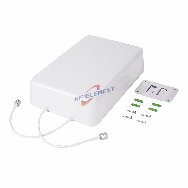
A compact log periodic dipole array for 698 to 4200 MHz in a 285 by 210 by 65 mm ABS housing, with 6 dBi at 698 MHz and 10.5 dBi at the top of the band. Polarization is vertical, the horizontal beam narrows from 80 degrees to 50 degrees across the range, and the single port is a 4.3-10 or N-Type female rated at 50 W. VSWR is 1.5 or better up to 2700 MHz and 1.8 or better above that. The unit weighs 0.8 kg and mounts on a pole.
285 mm is two thirds of a wavelength at 700 MHz
The boom length sets how many elements are electrically active, and at 698 MHz the wavelength is 430 mm, so this antenna is only 0.66 wavelengths long. At 3900 MHz the same boom is 3.7 wavelengths. The gain curve follows that ratio: 6 dBi at the bottom, 7 dBi across 806 to 960 MHz, 9 dBi through 1710 to 2700 MHz and 10.5 dBi at 3800 to 4200 MHz.
The 9 dBi figure in the product description is the 1710 to 2700 MHz value, which is the sub band most DAS and booster designs are built around. The published maximum of 10.5 dBi belongs to the 3800 to 4200 MHz range. Both are on the table below, and reading the curve rather than a single headline number is the only way to compare this antenna with a longer one.
The band where it beats the long version
VSWR is 1.5 or better from 698 all the way to 2700 MHz. The 442 mm version holds 1.5 only to 960 MHz and then sits at 1.8 for the rest of the band. At 1710 to 2700 MHz that is a mismatch loss of 0.18 dB against 0.37 dB, so the shorter antenna is the better matched of the two in the middle band even though it gives up 2 dB of gain there.
That trade is worth making when the radios are already at the limit of their output and the feeder is long. A 0.19 dB improvement is small on its own, but it comes with 0.4 kg less mass and 157 mm less boom, which changes the bracket and the wind load rather than just the loss budget.
| Frequency Range | 698-4200MHz | ||||
| Frequency Sub-Range(Mhz) | 698-806 | 806-960 | 1710-2700 | 3300-3800 | 3800-4200 |
| Polarization | Vertical | ||||
| Gain(dBi) | 6±0.5 | 7±0.5 | 9±0.5 | 10±0.5 | 10.5±0.5 |
| Horizontal Beam width | 80±5° | 70±5° | 60±5° | 55±5° | 50±5° |
| Vertical Beam width | 60±5° | 55±5° | 50±5° | 45±5° | 40±5° |
| Impedance | 50Ω | ||||
| VSWR | ≤ 1.5 | ≤ 1.5 | ≤ 1.5 | ≤1.8 | ≤1.8 |
| Maximum Power | 50 W | ||||
| Connector Type | 1 Port, 4.3-10 Female or N-Type Female | ||||
| Length | 285 mm | ||||
| Width | 210 mm | ||||
| Depth | 65 mm | ||||
| Net Weight | 0.8 kg | ||||
| Operating Temperature | -55° to +60° C (-67° to +140° F) | ||||
| Radome Material | Plastic ABS | ||||
| Radome Color | White | ||||
| Mounting Options | Pole mounting | ||||
Where the short boom stops being enough
The 6 dBi at 698 MHz is the number that decides the application. A 700 MHz coverage cell planned around a 9 dBi antenna loses 3 dB at the cell edge if this one is substituted, which is roughly a 30 percent reduction in radius in a cluttered environment. If any carrier in the plan sits below 960 MHz, the longer version is the correct choice and the extra mass is not negotiable.
Above 1710 MHz the difference shrinks to 2 dB and then to 1.5 dB. For a 3.5 GHz small cell, a CPE installation or an in-building DAS head end that only carries the mid and high bands, this antenna covers the whole 1710 to 4200 MHz span in a 65 mm deep housing with a better match than the long version.
0.8 kg on a light pole
The projected area is 285 by 210 mm, about 0.06 square metres, which gives roughly 40 N of drag at 30 m per second. That is light enough for a wall bracket, a slimline mast or a rooftop rail where a 1.2 kg antenna and its clamp would need additional fixing points.
The ABS radome is white and sealed, and the 65 mm depth means the antenna can be mounted on a narrow ledge without a standoff. Because a log periodic has no reflector, there is no back plate to keep clear of the wall, which is often the reason a panel of similar gain cannot be used in the same position.
Ordering
The connector is 4.3-10 female or N-Type female, polarization is vertical, and the bracket suits a 40 to 50 mm pole. Samples in 3-5 days, production in 15-25 days.
Where 700 or 800 MHz coverage is in the plan, the 442 mm LPDA version adds 3 dB at the bottom of the band for 0.4 kg more mass. For the broader product family, see 5G antenna.
Send the lowest carrier in the plan, the pole diameter and the feeder length. The lowest carrier decides between the two boom lengths, the pole decides the bracket, and the feeder length decides whether the better match of this version is worth the 2 dB it gives up. For a side by side view of boom lengths, gains and connectors across the band, the antenna selector filters the catalogue by frequency and gain.
FAQ — 5G LPDA Antenna
What is the 5G LPDA Antenna used for?
What frequency band does the 5G LPDA Antenna cover?
What are the key specifications of the 5G LPDA Antenna?
Can RF element customize the 5G LPDA Antenna for my application?
What is the MOQ and lead time for the 5G LPDA Antenna?
How do I get a quotation for the 5G LPDA Antenna?