
4G LTE MIMO Sector Antenna | ±45 Degree Cross-Polarized Sector Antenna
Specifications
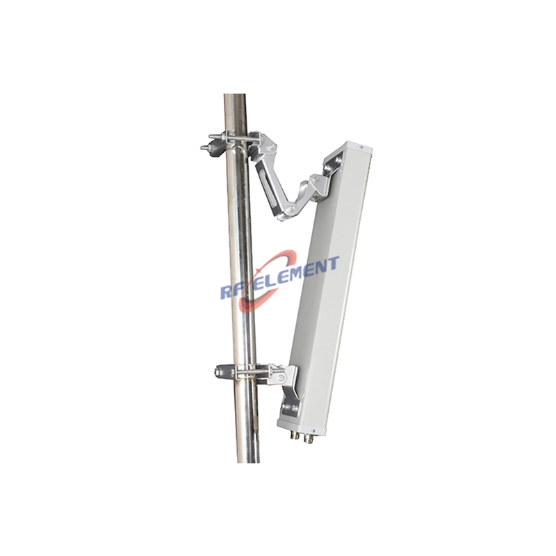
A 65 degree sector for 698-2700 MHz with a cross polarized pair of N-Type female ports and a front to back ratio above 20 dB. Gain is 7 dBi at 698-960 MHz and 9 dBi at 1710-2700 MHz, the vertical beam is 65 degrees in both sub bands, VSWR is at or below 1.8, and the rating is 100 W. The radome is grey PVC, the body measures 450 by 280 by 180 mm, and the unit weighs 2.5 kg for pole mounting.
Sixty-five degrees and three sectors
Three sectors of 65 degrees give 195 degrees of nominal coverage, so adjacent beams overlap by about 15 degrees at the half power points. That overlap is the point: it holds the sector edge above the level where a handset drops to a lower modulation, and it lets the site hand a user from one sector to the next without a hole.
The datasheet figure is the one to plan with, 65 degrees plus or minus 5 in both sub bands. The 45 in the model name is not a beamwidth: it is the slant angle of the two ports, plus or minus 45 degrees, and it describes the polarization rather than the pattern. Beamwidth and polarization are separate numbers, and both appear on the table below.
A four sector site would use 90 degree panels instead, and the choice is usually made by capacity rather than by coverage: four sectors divide the same power into narrower slices and raise the spectral efficiency per square kilometre, at the cost of more feeders and more baseband.
Front to back above 20 dB
Front to back ratio is what a sector radiates backwards relative to its peak. Above 20 dB means the back lobe is less than one hundredth of the forward power, so a panel mounted on a mast does not illuminate the mast itself or the sector behind it. On a co-located site with three operators on one tower, that figure decides whether the sectors can share a mounting level.
It also decides the reuse distance. A 20 dB front to back ratio lets the same frequency be reused on the opposite face of the same building; a 12 dB panel would require a different channel or a different site. The grey PVC radome does not contribute to this figure, but a metal bracket bolted across the back of the housing will destroy it, so mount on the supplied clamp and keep the rear face clear.
| Frequency Range | 698-2700MHz | |
| Frequency Sub-Range | 698-960 MHz | 1710-2700 MHz |
| Polarization | ±45° | |
| Gain(dBi) | 7 | 9 |
| Horizontal Beamwidth | 65±5° | |
| Vertical Beamwidth | 65±5° | |
| Impedance | 50Ω | |
| VSWR | ≤ 1.8 | |
| Front to Back Ratio(dB) | >20 | |
| Maximum Power | 100W | |
| Connector Type | 2 Port, N-Type Female | |
| Antenna Dimension(mm) | 450*280*180 | |
| Net Weight | 2.5 kg | |
| Operating Temperature | -55° to +60° C (-67° to +140° F) | |
| Radome Material | PVC | |
| Radome Color | Gray | |
| Mounting Options | Pole mounting | |
Cross polarization and 2x2 MIMO
The two ports are fed at plus 45 and minus 45 degrees, which is the standard cellular arrangement. A handset in a scattering environment sees both slants with similar strength, so the baseband can separate the two streams by polarization rather than by angle. This is why a cross polarized sector delivers rank 2 more reliably than a pair of vertically polarized panels spaced along a mast.
The figure that matters is the cross polarization discrimination, and it degrades with every metre of cable that is not kept matched. Use the same cable type and the same length on both ports, and torque both connectors to the same value. A 1 dB difference between the two branches costs more throughput than 1 dB of antenna gain.
450 by 280 by 180 and 2.5 kg
A 450 mm width sets the azimuth beamwidth and a 180 mm depth sets the front to back ratio. The 2.5 kg mass and the 0.13 square metre frontal area are within the range of a single pole clamp on a 50 mm mast, which is why this housing is used for small cell and DAS donor antennas rather than for macro sites.
The table lists pole mounting only. If the site needs a specific mechanical downtilt, state the angle at order and we will confirm the bracket that achieves it. Do not plan on shimming the clamp: a 65 degree vertical beam tolerates a few degrees of error, but a shim that slips changes the coverage without anyone noticing.
DAS donor and small cell
The usual job for this panel is the donor link of an indoor DAS: one sector pointed at the serving macro, feeding a repeater or a small base station inside the building. For that job the front to back ratio matters more than the gain, because the donor signal is usually strong enough and the risk is picking up a second cell on the back lobe.
For a small cell on a pole, the same panel covers a street segment. 9 dBi at 2.6 GHz with a 65 degree horizontal beam reaches about 300 m along a street with a 5 W radio, which is a typical small cell radius and keeps the cell edge above the noise floor.
Ordering
Two N-Type female ports on the slant pair, grey PVC radome, pole clamp. Samples in 3-5 days, production in 15-25 days.
Where the site needs a full 360 degree pattern instead of a sector, the 4G LTE MIMO omni antenna 698-2700 MHz serves the same band plan from one pole. Where the requirement is high gain in a narrow sector with a single polarization, the 4G LTE 90 degree sector antenna reaches 15 dBi.
Send the sector count, the tilt and the feeder length. The sector count fixes the beamwidth, the tilt fixes the bracket, and the feeder length decides whether 9 dBi survives the run to the radio.
FAQ — 4G LTE MIMO Sector Antenna
What is the 4G LTE MIMO Sector Antenna used for?
What frequency band does the 4G LTE MIMO Sector Antenna cover?
What are the key specifications of the 4G LTE MIMO Sector Antenna?
Can RF element customize the 4G LTE MIMO Sector Antenna for my application?
What is the MOQ and lead time for the 4G LTE MIMO Sector Antenna?
How do I get a quotation for the 4G LTE MIMO Sector Antenna?