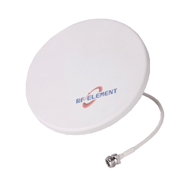

5G Ceiling Antenna | Indoor 5G Booster Antenna | Full Bands 698-6000MHz
Maximize your in-building wireless connectivity with RF element's Ultra Wide Band 5G Ceiling Mounting Antenna. This versatile antenna covers 698-6000MHz, supporting 5G, 4G/LTE, 3G, and GSM applications. Its easy installation and multiband design make it perfect for DAS systems. Contact us for a quote today!
Specifications
One ceiling antenna that covers 698 MHz to 6 GHz, including the 5150-6000 MHz window that most cellular ceiling units stop short of. The point is not the headline range but the overlap: a single passive layer can carry 5G, LTE, Wi-Fi 5, Wi-Fi 6 and Wi-Fi 6E without a second antenna type on the same ceiling grid, which matters in venues where the cellular DAS and the Wi-Fi network are installed by different contractors on the same programme.
Why the 5-6 GHz window is separate
Wi-Fi 6E opened 5925-7125 MHz in several markets, and the 5150-6000 MHz band already carried Wi-Fi 5 and 6. A ceiling antenna designed for cellular stops at 3.8 or 4.2 GHz, so the Wi-Fi layer needs its own units, its own cable runs and its own ceiling penetrations. Extending the same radiator to 6 GHz removes that duplication at the cost of housing depth: this unit is 120 mm tall, against 12-18 mm for a cellular-only disc.
Where the ceiling void is shallow, that depth is the deciding constraint and a two-antenna solution is the only option. Where there is a service void of 150 mm or more, one unit per position is cheaper to install and easier to document.
Pattern across seven octaves
Gain moves from 1.5 dBi at 698-806 MHz to 5.5 dBi from 3.3 GHz upward, and vertical beamwidth narrows from 90 to 40 degrees over the same span. That is a normal progression for a multiband radiator, but it means the coverage radius at 6 GHz is set by the pattern, not by the gain: a 40 degree beam at a 3 m ceiling covers roughly the same floor area as the 90 degree beam in the low band, which is convenient for layout but leaves the high band with less overlap at the cell edge.
| Frequency Range | 698-6000MHz | |||||
| Frequency Sub-Range(Mhz) | 698-806 | 806-960 | 1710-2700 | 3300-3800 | 3800-4000 | 5150-6000 |
| Polarization | Vertical | |||||
| Gain(dBi) | 1.5±0.5 | 2.2±0.5 | 3.5±0.5 | 4.5±0.5 | 5.5±0.5 | 5.5±0.5 |
| Horizontal Beam width | 360° | |||||
| Vertical Beam width | 90±10° | 85±10° | 65±10° | 40±20° | 40±20° | 40±20° |
| Impedance | 50Ω | |||||
| VSWR | ≤ 1.8 | ≤ 1.5 | ≤ 1.6 | ≤ 1.6 | ≤1.6 | ≤1.6 |
| Maximum Power | 50 W | |||||
| Connector Type | 1 Port, 4.3-10 Female or N-Type Female | |||||
| Length | 185 mm | |||||
| Width | 185 mm | |||||
| Depth | 120 mm | |||||
| Net Weight | 0.4 kg | |||||
| Operating Temperature | -55° to +60° C (-67° to +140° F) | |||||
| Radome Material | Plastic ABS | |||||
| Radome Color | White | |||||
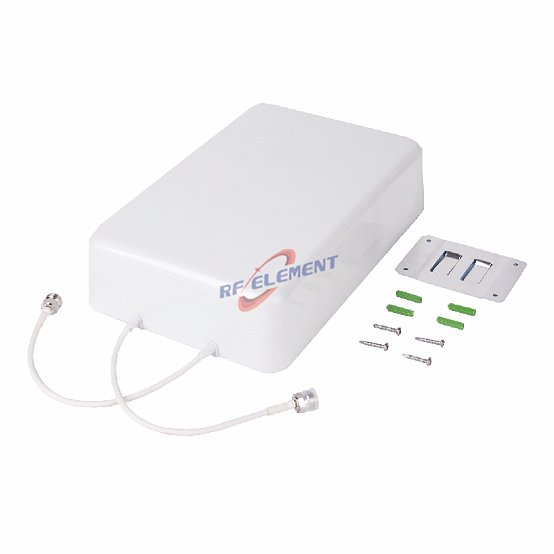
| Mounting Options | fasteners and screws included for wall mounting | |||||
Return loss is at or below 1.8 at the bottom of the band and 1.5-1.6 above 806 MHz, with the loosest value at 698-806 MHz. For a Wi-Fi-led design that is irrelevant; for a 700 MHz cellular layer it is worth confirming against the remote unit's tolerance.
What it changes for the installer
One cable per position instead of two, one connector type, one test record. On a 200-position ceiling that is 200 fewer penetrations and 200 fewer joints to torque, and it removes the coordination problem of two contractors claiming the same grid module. The trade is that a failure affects both networks, so the passive layer should be documented as shared infrastructure rather than owned by either system.
Because the body is 120 mm deep, the ceiling must have a clear void or a surface mount. On a plasterboard ceiling with no service gap this unit cannot be fitted; the alternative is a 12-18 mm cellular disc plus separate Wi-Fi access points.
Power and PIM
Maximum power is 50 W and the connector is a single 4.3-10 or N-Type Female. There is no PIM figure quoted for this model, which is consistent with a wideband design intended for combined cellular and Wi-Fi use rather than a multi-operator passive layer. Where the installation is a shared cellular DAS with high carrier power per port, choose a low PIM unit instead and keep Wi-Fi on a separate layer.
Alternatives by band plan
If the band plan stops at 4.2 GHz, the 698-4200 MHz wideband plate does the same job in a 15 mm body at less cost. If the plan stops at 4.0 GHz, the 698-4000 MHz indoor unit adds low PIM at the same depth. This model is the only one in the range that reaches 6 GHz.
Customisation and ordering
Connector type, radome colour and packing quantity are selectable. The 698-6000 MHz span and 120 mm body are fixed. Samples in 3-5 days, production in 15-25 days.
Send the Wi-Fi band plan and the ceiling void depth. If the Wi-Fi design uses 6 GHz, this is the only unit in the range that covers it; if it does not, a cellular-only disc will do the same job for less.
FAQ — 5G Ceiling Antenna
What is the 5G Ceiling Antenna used for?
What frequency band does the 5G Ceiling Antenna cover?
What are the key specifications of the 5G Ceiling Antenna?
Can RF element customize the 5G Ceiling Antenna for my application?
What is the MOQ and lead time for the 5G Ceiling Antenna?
How do I get a quotation for the 5G Ceiling Antenna?