
4G LTE Omni Antenna | Outdoor Low PIM Rated Omni Antenna
Specifications
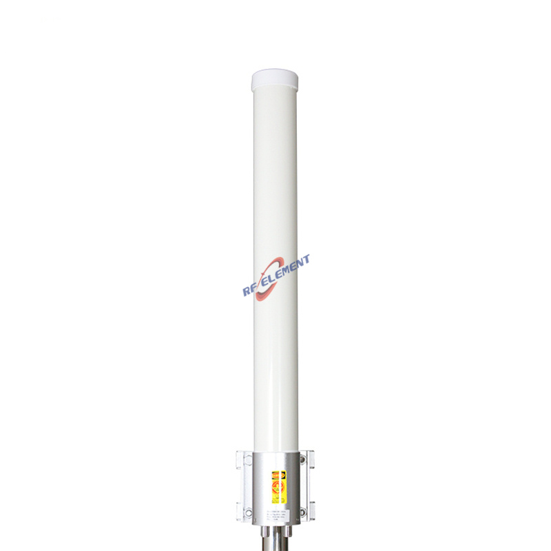
A 1200 mm fibreglass omni for 698-2700 MHz with a third order PIM rating of 150 dBc at 2x20 W and a single 7/16 DIN port. Gain is 4 dBi at 698-960 MHz and 6.5 dBi at 1710-2700 MHz, the horizontal pattern is a full 360 degrees, the vertical beam is 75 degrees and 25 degrees, VSWR is at or below 1.8, and the rating is 100 W. It weighs 2.5 kg and is the omni to specify where several transmitters share one mast.
What 150 dBc actually means on site
Two carriers at 43 dBm each in a nonlinear joint produce a third order product at 2f1 minus f2. A rating of 150 dBc means that product sits 150 dB below the carrier, so at 43 dBm per carrier the source level is about minus 107 dBm. A receiver with a 2 dB noise figure has a noise floor near minus 119 dBm in a 200 kHz channel.
That arithmetic explains why the number is quoted at all: even a 150 dBc antenna leaves the product about 12 dB above the noise floor before any cable loss is counted, and cable loss works in your favour on the way to the receiver. A 130 dBc antenna would leave it 32 dB above the floor, which is enough to desense a weak uplink. The figure is a floor to stay above, not a luxury.
7/16 DIN instead of N
PIM is generated at the current density discontinuity in a connector, so the interface is the part that decides it. A 7/16 DIN has a much larger contact area than an N-Type and a threaded body that stays tight under vibration, which is why it is the standard interface on low PIM hardware. It is also the reason this antenna is not offered with an N-Type on the same rating.
Torque matters as much as the interface. A 7/16 DIN wants about 20 to 25 Nm, well beyond hand tight, and an under torqued joint will produce more PIM than a correctly torqued N-Type. Use a torque wrench, and re-check after the first thermal cycle if the site sees a wide temperature swing.
| Frequency Range | 698-2700MHz | |
| Frequency Sub-Range | 698-960 MHz | 1710-2700 MHz |
| Polarization | Vertical | |
| Gain(dBi) | 4 | 6.5 |
| Horizontal Beamwidth | 360° | |
| Vertical Beamwidth | 75° | 25° |
| Impedance | 50Ω | |
| VSWR | ≤ 1.8 | |
| Maximum Power | 100W | |
| 3rd PIM(2x20W) (dBc) | 150 | |
| Connector Type | 1 Port, 7/16 DIN | |
| Antenna Dimension(mm) | Φ 52*1200 | |
| Net Weight | 2.5 kg | |
| Operating Temperature | -55° to +60° C (-67° to +140° F) | |
| Radome Material | Fiberglass | |
| Radome Color | White | |
| Mounting Options | Pole mounting | |
1200 mm of fibreglass and a 25 degree beam
At 698 MHz the 1200 mm radome is under three wavelengths, so the collinear array has few elements and the vertical beam stays at 75 degrees. At 2.6 GHz the same length is more than ten wavelengths, the array has many elements, and the beam narrows to 25 degrees while the gain rises from 4 dBi to 6.5 dBi.
The narrow high band beam is the trade for the low band coverage. On a mast serving both bands, the 2.6 GHz coverage becomes a ring whose radius depends on the mounting height, while the 700 MHz coverage is a broad lobe. Plan the two bands as two different coverage shapes rather than assuming one pattern serves both.
Fibreglass in a coastal site
Filament wound fibreglass holds its colour and does not chalk the way a painted ABS tube does, and it keeps its mechanical strength at the top of the -55 to +60 C range. The 2.5 kg mass is concentrated at the base connector, so the clamp carries the load at the point where the radome is thickest.
Sea air attacks the clamp and the connector, not the radome. Specify stainless hardware for a coastal site and re-grease the 7/16 DIN threads at each service visit. A corroded joint is also a PIM source, so the maintenance routine protects the electrical performance rather than only the appearance.
Single port and what it rules out
One port means no MIMO. If the radio expects two branches, this antenna cannot feed them, and no amount of gain compensates for a missing second stream in a capacity limited cell. The low PIM requirement and the MIMO requirement pull in different directions, and the usual resolution is a dual port low PIM model rather than this one.
Where the site is a repeater, a single carrier base station or a telemetry link, the single port is not a limitation at all. It removes one jumper, one connector pair and one source of PIM, which is exactly the point of the part.
Ordering
One 7/16 DIN port, white fibreglass radome, pole mount, stainless hardware on request. Samples in 3-5 days, production in 15-25 days.
Where the low PIM requirement is indoors, the 5G low PIM ceiling antenna 150 dBc carries the same rating in a 90 mm ceiling housing. Where the site needs two branches and does not carry multiple high power carriers, the 4G LTE MIMO omni antenna 698-2700 MHz is the dual port alternative.
Send the carrier frequencies, the power per carrier and the receive band you are protecting. The PIM product only matters if it lands in that receive band, and the answer decides whether 150 dBc is sufficient or whether the site needs a different antenna position instead.
FAQ — 4G LTE Omni Antenna
What is the 4G LTE Omni Antenna used for?
What frequency band does the 4G LTE Omni Antenna cover?
What are the key specifications of the 4G LTE Omni Antenna?
Can RF element customize the 4G LTE Omni Antenna for my application?
What is the MOQ and lead time for the 4G LTE Omni Antenna?
How do I get a quotation for the 4G LTE Omni Antenna?