
Choosing the Right Antenna for Point-to-Point and Point-to-Multipoint Systems
A point-to-point link is decided by a link budget, and the antenna is only the last line in it. Distance, obstruction, fresnel clearance and the data rate the customer actually needs are settled before any gain figure makes sense, and the dish that closes a 12 km hop across open country will fail at 2 km in a city because the far end has moved from where the drawing put it. We build grid, dish, panel, sector and omni antennas into those budgets, and the numbers below are the ones printed on our own datasheets.

Two questions before anything is ordered
The first is whether the far end ever moves. If it does, the beam has to be wide enough to keep the link while the customer moves through it, and that immediately rules out the narrow end of the range. The second is how much structure the site will carry. A dish of that size weighs 12 kg and presents a wind load a 60 mm pole will not survive, so the mount is settled before the model is. Answer those two and the choice narrows to two or three models; skip them and the project buys gain it cannot point.
Point to point: gain buys distance and very little else
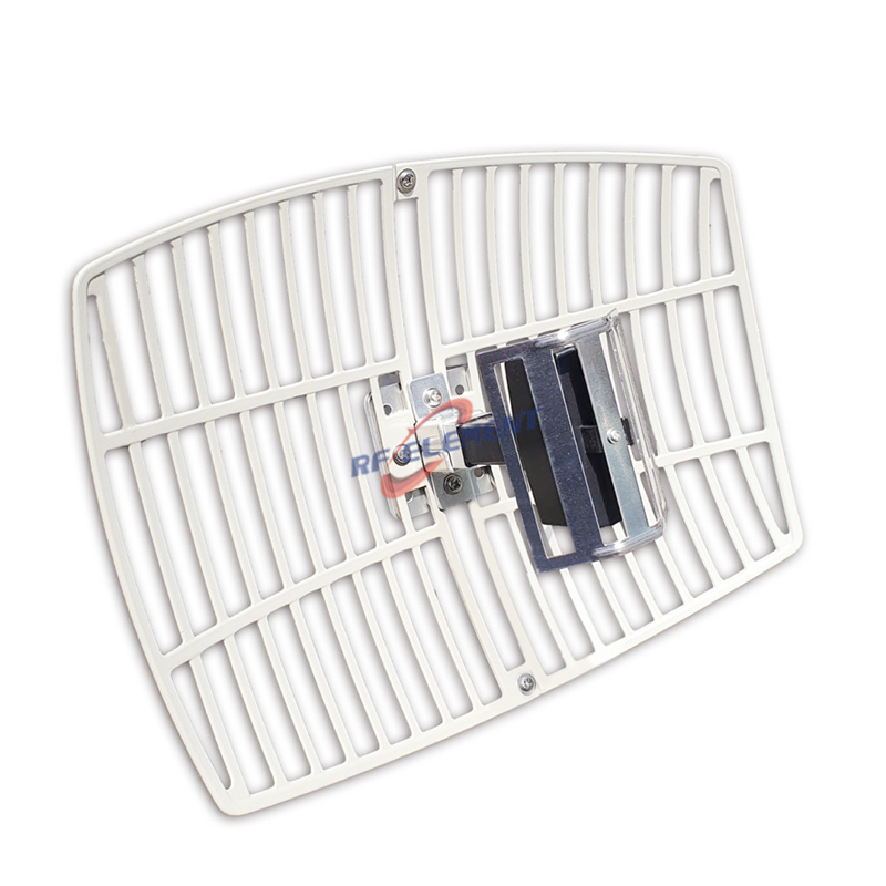
A 15 dBi dual band parabolic grid covers 2400-2500 MHz in a 16 degree horizontal and 21 degree vertical pattern, VSWR within 1.5, handles 50 W, measures 300 by 400 mm at 1.2 kg, and is the smallest grid we would put on a short urban hop. The larger grid in the same family tightens that to 12 and 15 degrees from a 600 by 900 mm reflector at 3.2 kg, which is the point where a two-person install becomes a one-person install with a ladder and a bad afternoon.
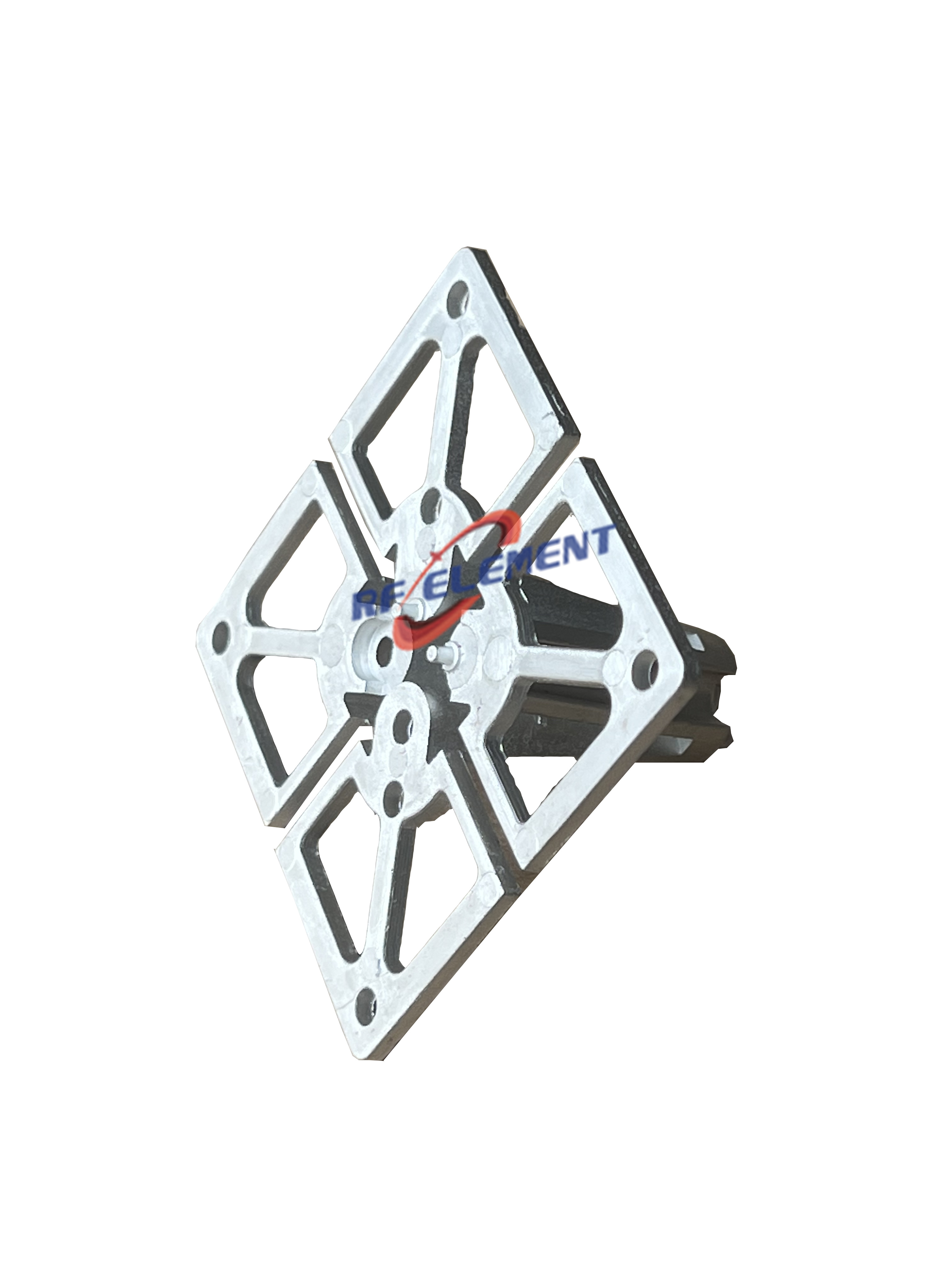
Above 4.9 GHz the geometry gets cheaper. A 5 GHz parabolic dish delivers 28 dBi with a 5 degree beam in both planes, suppressing the rear response by at least 32 dB, on a 60 cm aluminium dish that weighs 7 kg, with 30 dB of cross-polar isolation and N-type female connectors on two ports behind a 100 W rating. Where the path is short but the interference is not, a 5 GHz bridge plate puts 18 dBi into a wedge 30 degrees wide and 20 degrees tall from a flat panel 305 mm square and 25 mm deep, and a cast housing version wraps the same plate when the radio has to be kept out of sight.
A narrow beam turns alignment into civil works
Beamwidth and pointing tolerance are the same number seen from two sides. A dish at 31 dBi holds a 4 degree horizontal and 3 degree vertical beam, and its 900 mm dish weighs 12 kg; a pole that sags half a degree under summer sun moves the far end of a 10 km path far enough off centre to cost link margin. This is why the mast deserves as much thought as the distance. A wide panel forgives a sloppy mount; a narrow dish does not, and the cost arrives later, as a repeat site visit rather than a larger invoice on the day of installation.
Point to multipoint: the vertical lobe decides coverage
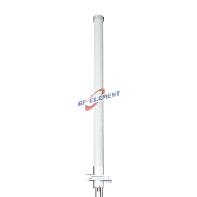
For a single access point serving scattered clients, the horizontal pattern is 360 degrees for every omni, so the useful discriminator is the vertical lobe. A 5 GHz dual polarity MIMO omni delivers 12 dBi into a 7 degree vertical lobe from a 75 mm radome 650 mm tall at 2.0 kg, which throws coverage out to the horizon and leaves a dead zone directly underneath. A 2.4 GHz MIMO omni trades 1 dBi for an 8 degree lobe and a 1150 mm body at 3.2 kg, and a 4G LTE MIMO omni goes the other way with 4 dBi of gain over a 60 degree vertical beam, which is the part for clients that sit close to the mast and below it rather than far away at the same height.
Sectors when the coverage area is not a circle
An omni spends two thirds of its power on directions with nobody in them. A 5 GHz MIMO sector antenna puts 19 dBi across a 90 degree horizontal sector and a 7 degree vertical beam, from a PVC body 770 mm long, 115 mm wide and 60 mm deep at 3.0 kg, and three of them on one mast cover a site with more gain than a single omni and better isolation between the radios. The trade is that sector coverage is planned, not assumed, and the plan has to be right before the first bracket goes up.
Two numbers that decide a link without appearing on the box
Every model in this article lists gain, beamwidth and impedance. None of them lists the two figures that decide whether a link holds. The first is fresnel clearance: a path needs an unobstructed zone around its centre line, and that zone grows with distance and shrinks with frequency. A 21 dBi grid on a 4 km hop needs clearance measured in metres at the midpoint, and a rooftop parapet standing inside that zone costs more link margin than the gap between a 15 dBi and a 21 dBi antenna would recover. The second figure is the radiated power the regulator allows at the transmitting end. A narrow beam concentrates energy, so in several administrations the permitted ceiling is reached at a transmitter setting well below what the radio can deliver, which means the additional gain buys nothing the customer is allowed to use.
The mount is part of the antenna
A beam that is pointed badly performs like a beam with less gain. Two degrees of error on a 5 degree dish moves most of the main lobe off the far end, while the same two degrees on a 90 degree sector is barely measurable, which is why the mounting hardware deserves the same attention as the antenna itself. We supply an adjustable pole mount that swings through 120 degrees of tilt on a 35 mm tube with 220 mm of reach at 0.8 kg, in aluminium or steel, and the reason it exists is that most installers align to a visible landmark rather than to a compass bearing. Where the pole itself flexes, no bracket compensates, and a tower survey costs less than a second visit with a crane.
Where one antenna type is the wrong answer
A high-gain grid is the wrong part when either end moves, when the path crosses mature trees at a shallow angle, or when the only available mount is a wooden post that will shift with the seasons. An omni is the wrong part when the site is long and thin, because half its power goes sideways into properties that will complain, and a sector is the wrong part when the client list is three sites spread over 340 degrees. The dish sits at the wrong end of the range whenever the customer cannot describe the far end's position within a few degrees, and no type works when the radio behind it cannot deliver the transmit power the budget assumed.
What to send us
Send the distance, the obstruction profile between the two ends, the mast height the site will really allow, and whether the far end ever moves. Put those four lines in one message to sales@rfelement.com, and what comes back names a model and a way of fixing it rather than a product family. If a radio is already installed, say which one, because its output power and port count constrain the choice more than the path does.
TAG:Choosing the Right Antenna for Point-to-Point and Point-to-Multipoint Systems https://www.rfelement.com