

Low PIM Rated Antenna
Welcome to the RF element Low PIM Rated Antenna product center. As a professional low-PIM rated antenna manufacturer, we are dedicated to delivering reliable low-PIM antenna solutions. Our products utilize advanced materials and innovative designs to minimize passive intermodulation (PIM) interference (typical value <-150 dBc), ensuring signal integrity for critical systems including 5G/4G networks and public safety communications.
Our Low-PIM-antenna portfolio includes:
- Low-PIM rated Base Station Antennas: For macro and small cell deployments, supporting 698–3800 MHz bands.
- Low-PIM rated Indoor Antennas: Designed for indoor coverage with low profile and easy installation.
- Low-PIM rated MIMO Antennas: Enhancing network capacity with 2x2/4x4 MIMO and multiple configurations.
Every product is validated through strict PIM testing and anechoic chamber evaluation, guaranteeing exceptional performance. Whether you need standard products or customizedLow-PIM-antennasolutions, our engineering team is ready to provide expert support. Contact us for a quote.
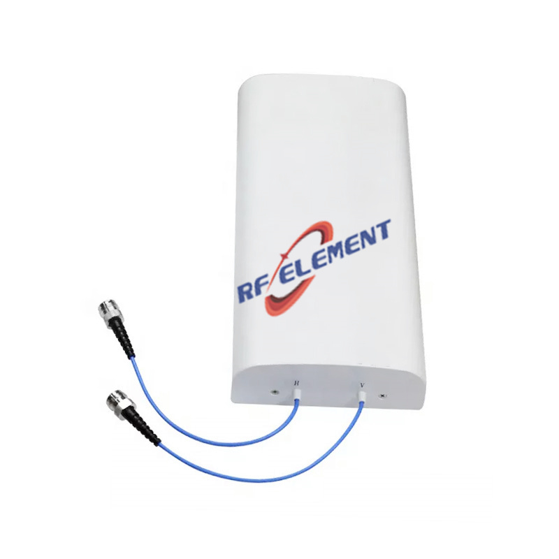
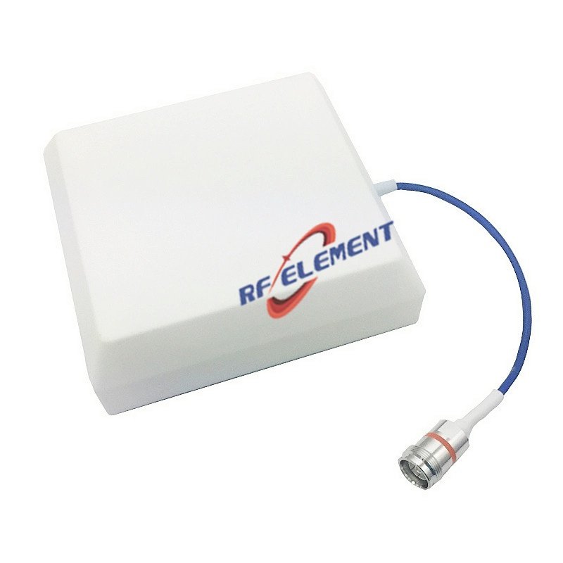
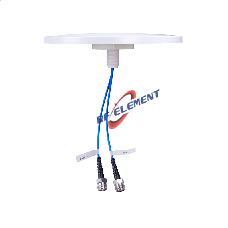
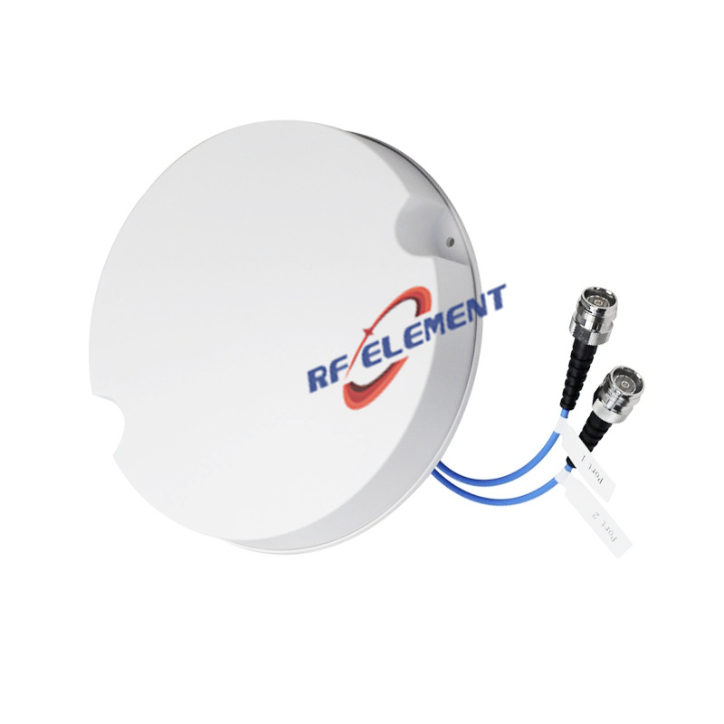

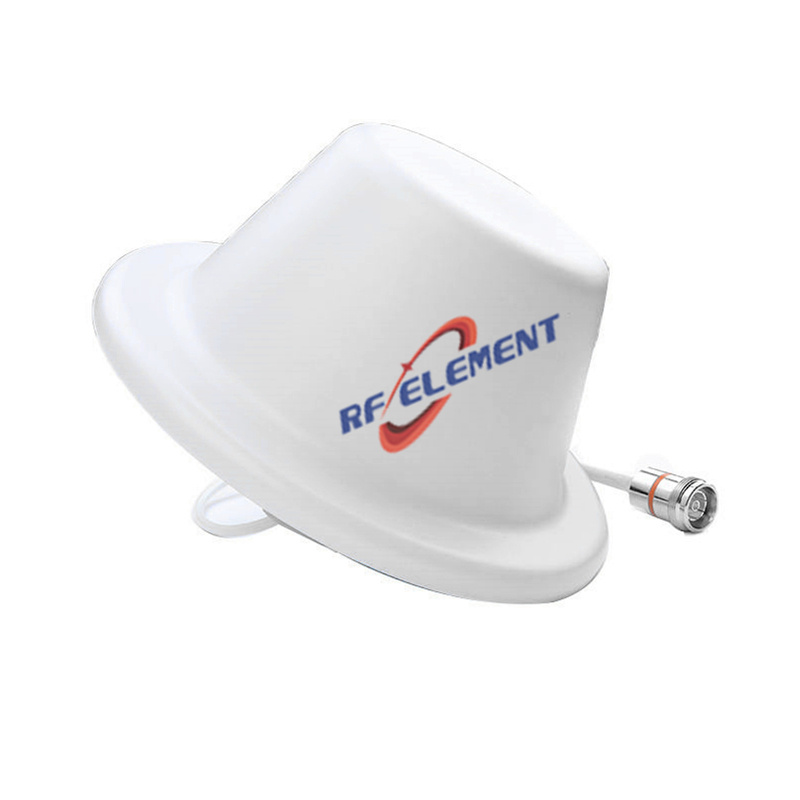


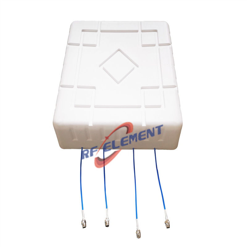
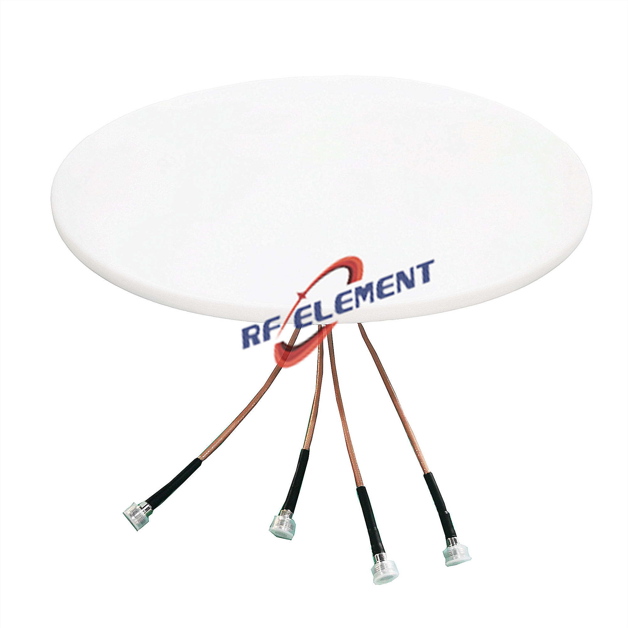
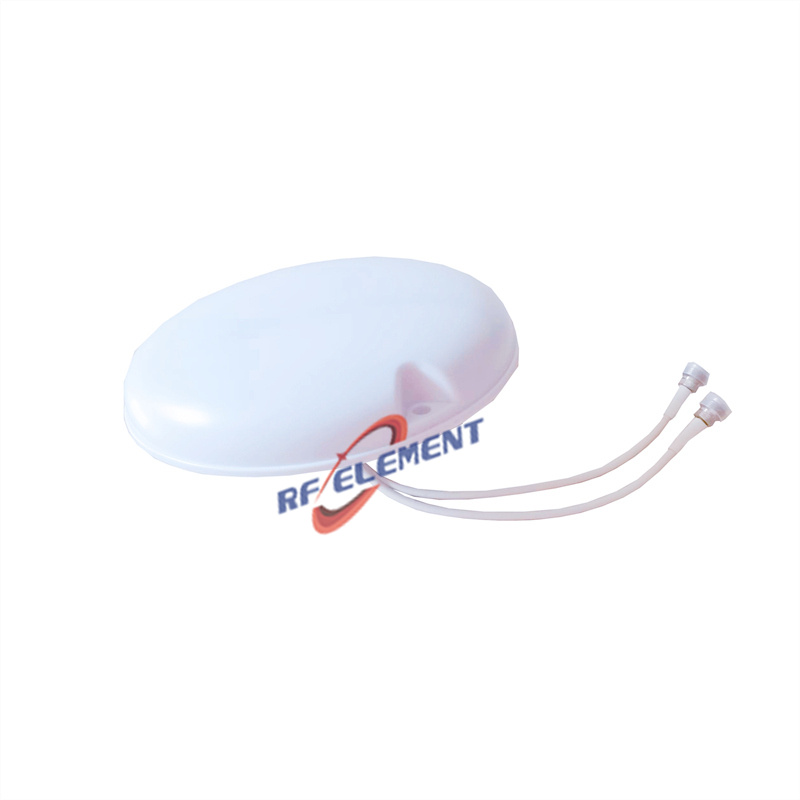



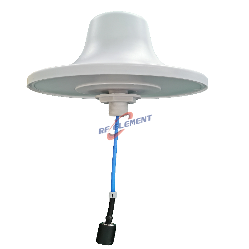
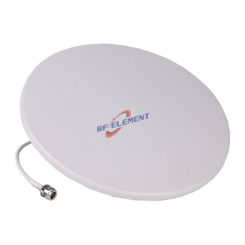

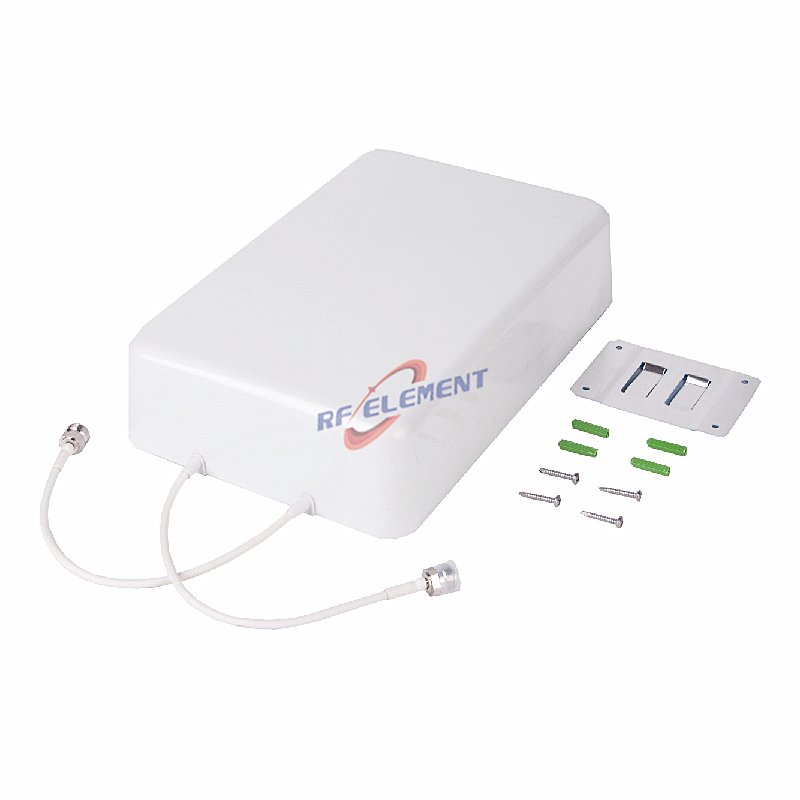


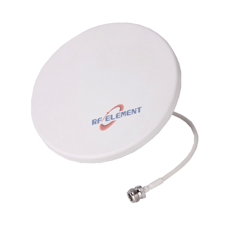

Low PIM Antenna Selection Guide
All models on this page side by side, with the specified third-order PIM value shown for each rated type. Use the PIM and gain columns to match the antenna to the carrier power in your DAS or small cell design.
| Model | Type | Frequency | Gain (dBi) | PIM, 3rd order | Size (mm) | Best for |
|---|---|---|---|---|---|---|
| Indoor Dome Ceiling Antenna | Indoor Ceiling, omni | 698-3800MHz | 1.5 - 5 | -150dBc@2×43dBm | Φ186 × 85 | In-building DAS, small cell and repeater coverage |
| Indoor Drop Ceiling Antenna | Indoor Ceiling, omni | 698-4000MHz | 1.5 - 4 | -150dBc@2×43dBm | Φ203 × 115 | In-building DAS, small cell and repeater coverage |
| Indoor 4X4 MIMO Ceiling Mounting Omni Antenna | Indoor Ceiling, omni, MIMO | 698-4200MHz | 1.5 - 5.5 | -153 dBc | 385 × 385 × 13 | In-building DAS, small cell and repeater coverage |
| Indoor Full Frequency Bands Ceiling Mounting Omni Antenna | Indoor Ceiling, omni | 698-6000MHz | 1.5 - 5.5 | — | 185 × 185 × 120 | In-building DAS, small cell and repeater coverage |
| Indoor Slim Full Frequency Bands Ceiling Mounting Omni Antenna | Indoor Slim ceiling, omni | 380-3800MHz | 1.5 - 5 | — | 280 × 280 × 18 | In-building DAS, small cell and repeater coverage |
| Indoor Ultra Wide Band MIMO Ceiling Mounting Omni Antenna | Indoor Ceiling, omni, MIMO | 698-4200MHz | 1.5 - 5.5 | -153 dBc | 280 × 280 × 15 | In-building DAS, small cell and repeater coverage |
| Indoor Ultra Wide Band SISO Ceiling Mounting Omni Antenna | Indoor Ceiling, omni | 698-4200MHz | 1.5 - 5.5 | -153 dBc | 180 × 180 × 12 | In-building DAS, small cell and repeater coverage |
| Indoor Wide Band MIMO Ceiling Mounting Omni Antenna | Indoor Ceiling, omni, MIMO | 698-3800MHz | 2 - 5 | — | 215 × 215 × 41 | In-building DAS, small cell and repeater coverage |
| Indoor Low Profile MIMO Ceiling Antenna | Indoor Slim ceiling, omni, MIMO | 698-3800MHz | 2.5 - 4 | -150dBc@2×43dBm | Φ280 × 15 | In-building DAS, small cell and repeater coverage |
| Indoor MIMO Ceiling Antenna | Indoor Ceiling, omni, MIMO | 698-3800MHz | 2.5 - 4.5 | -150dBc@2×43dBm | Φ215 × 42 | In-building DAS, small cell and repeater coverage |
| Indoor Low profile Slim Ceiling Antenna | Indoor Slim ceiling, omni | 698-3800MHz | 2.5 - 4 | -150dBc@2×43dBm | Φ186 × 15 | In-building DAS, small cell and repeater coverage |
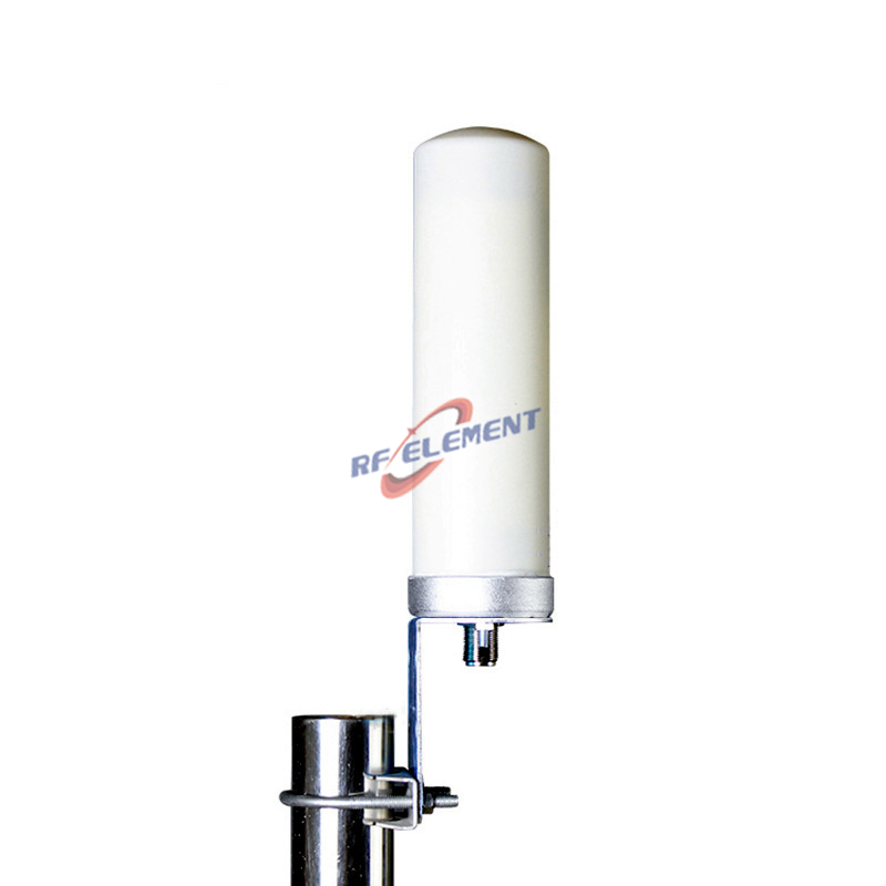
| Outdoor Ultra Wide Band Omni Antenna | Outdoor Omni, omni | 698-4200MHz | 3 - 5.5 | — | Φ60 × 250 | Wide-area 360° outdoor coverage |
| Outdoor Ultra Wide Band MIMO Directional Panel Antenna | Outdoor Panel, directional, MIMO | 698-4200MHz | 5 - 8 | -153 dBc | 310 × 230 × 73 | Focused area coverage or point-to-point |
| Indoor Ultra Wide Band MIMO Directional Panel Antenna | Indoor Panel, directional, MIMO | 698-4200MHz | 5 - 8 | -153 dBc | 310 × 230 × 73 | Focused area coverage or point-to-point |
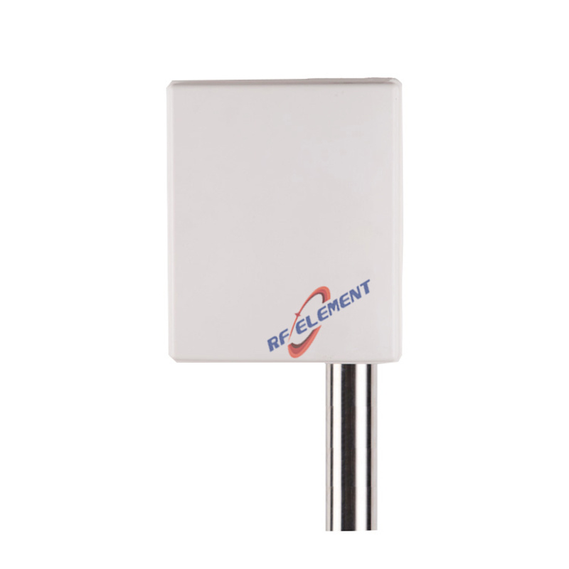
| Outdoor Ultra Wide Band Pole Mounting Directional Panel Antenna | Outdoor Panel, directional | 698-4200MHz | 5 - 7 | -153 dBc | 165 × 155 × 50 | Focused area coverage or point-to-point |
| Indoor Ultra Wide Band Wall Mounting Directional Panel Antenna | Indoor Panel, directional | 698-4200MHz | 5 - 7 | -153 dBc | 165 × 155 × 50 | Focused area coverage or point-to-point |
| MIMO Directional Panel Antenna | Panel, directional, MIMO | 698-3800MHz | 6 - 8 | -153 dBc@2×43dBm | 360 × 155 × 65 | Focused area coverage or point-to-point |
| Directional Panel Antenna | Panel, directional | 698-3800MHz | 6 - 7 | -153 dBc@2×43dBm | 165 × 155 × 45 | Focused area coverage or point-to-point |
| Outdoor Ultra Wide Band Log Periodic Directional Panel Antenna | Outdoor LPDA, directional | 698-4200MHz | 6 - 10.5 | — | 285 × 210 × 65 | Wideband sweep, monitoring and multi-band sites |
| Indoor 4X4 MIMO wall Mounting Panel Antenna | Indoor Panel, directional, MIMO | 617-4200MHz | 7.5 - 10.5 | -153 dBc | 450 × 450 × 110 | Focused area coverage or point-to-point |
| Dual Polarity Beautification Spotlight Antenna | Camouflaged spotlight, directional, MIMO | 800-3800MHz | 9 - 13 | — | 430 × 420 × 135 | Camouflaged macro site, low visual impact |
| Outdoor Ultra Wide Band Log Periodic Directional Panel Antenna | Outdoor LPDA, directional | 698-4200MHz | 9 - 12 | — | 442 × 210 × 65 | Wideband sweep, monitoring and multi-band sites |
| Outdoor Fiberglass Omni Antenna | Outdoor Omni, omni | 3400-3800MHz | 11 | — | Φ42 × 630 | Wide-area 360° outdoor coverage |
| Outdoor MIMO Directional Panel Antenna | Outdoor Panel, directional, MIMO | 3300-3800MHz | 12 | — | 239 × 190 × 35 | Focused area coverage or point-to-point |
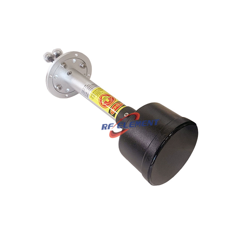
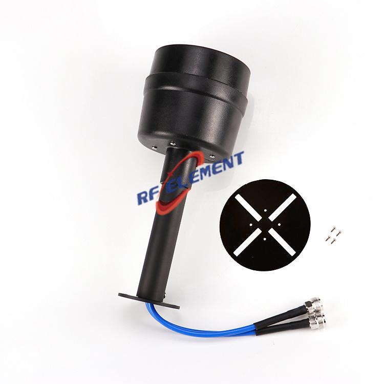
| Outdoor MIMO Feedhorn | Feedhorn for dish / grid | 3300-3800MHz | 23 | — | — | High-gain dish / grid feed for backhaul |
| Ultra Wide Band MIMO Feedhorn | Feedhorn for dish / grid | 1700-4200MHz | 25 - 28 | — | — | High-gain dish / grid feed for backhaul |
Tightening a PIM budget for a DAS or small cell deployment? Send the carrier power and the band through contact us and our engineers will confirm the PIM specification you need.
Where PIM Actually Comes From
Passive intermodulation is generated at a non-linear junction in the RF current path, not in the radiating element. It is also not a match problem: an antenna can hold 1.2:1 VSWR across the whole band and still be the worst PIM source on the site. In a DAS the two downlink carriers — 20 W each, 43 dBm — mix at that junction and produce the third-order products 2f1−f2 and 2f2−f1, which land inside the uplink band, exactly where the receiver is weakest.
| Junction | What goes wrong | What we do about it |
|---|---|---|
| Connector mating | Under-torqued or over-torqued coupling nuts, damaged threads, a plated brass body mated to a stainless jumper, no torque wrench on site | Machined connector body, a published torque figure, and one metal system from the antenna port through the supplied jumper |
| Plating | Thin silver over a nickel barrier, oxidised contact faces, gold flash on a surface that is never gold-to-gold | Silver or white-bronze on the current path; no nickel layer anywhere the RF current flows |
| Solder and crimp joints | Solder voids, flux residue, cold joints, a crimp made with the wrong die — each one is a diode in the current path | No soldered joint in the RF path; machined or welded construction, and crimps only with the matching die |
| Ferromagnetic material | Steel screws, nickel-plated hardware, iron brackets carrying current — the classic hidden source that no VSWR sweep will show | Non-ferromagnetic hardware in the current path; stainless steel only where it carries no RF current |
| Contamination and moisture | Metal filings from a drilled hole, a dust film on the element, condensation inside the radome | Sealed radome, controlled assembly, an IP-rated gasket and a drain path |
Why the Number Is Written in dBc — and Why 2 × 43 dBm Has to Travel With It
A PIM figure is quoted relative to the carrier, so the carrier power is part of the specification, not a footnote. 2 × 20 W is the same test condition as 2 × 43 dBm, and both appear on datasheets.
Third-order products rise roughly 3 dB for every 1 dB the carriers rise. That single fact invalidates most cross-datasheet comparisons: a figure of −155 dBc measured at 2 × 33 dBm is not better than −150 dBc at 2 × 43 dBm — normalised to the same carrier power it is about 30 dB worse. Ask what power the number was measured at before you rank two antennas.
−150 dBc with 43 dBm carriers → 43 − 150 = −107 dBm at the antenna port.
An LTE uplink at 5 MHz bandwidth has a reference sensitivity floor close to −100 dBm, so one PIM source at this level leaves about 7 dB of margin. Two sources plus a jumper and a lightning arrestor can consume it. That margin — not antenna gain — is what limits the uplink of an in-building cell.
What to Ask For in the Test Report
- Carrier power and order — 2 × 43 dBm, third order, stated on the page next to the number.
- A swept measurement, not a single point — PIM varies with channel position, so a figure at mid-band says nothing about the band edges.
- Every port and both polarisations — a 2 × 2 MIMO panel has four paths to characterise, and the worst one is the specification.
- Measured, not simulated, and to IEC 62037 — that is the intermodulation measurement standard a carrier's acceptance engineer will ask about.
- With the supplied jumper fitted — a low-PIM antenna joined to a lossy jumper measures the jumper, which is why we quote the assembly.
What to Send with an RFQ
- Band and carrier power — the downlink carriers per port, so the PIM level and the power handling are specified against your real condition.
- PIM target and test condition — for example −150 dBc at 2 × 43 dBm, third order.
- Antenna type and mounting — indoor ceiling for a DAS, outdoor panel or feedhorn for a small cell or repeater.
- MIMO order and connector — 2 × 2 or 4 × 4, 4.3-10 or N-type, with the jumper you intend to use.
- Project volume — the annual quantity per variant, so the plating and connector build is quoted once.
Send those details to our engineering team for a model recommendation, a measured PIM report and a quotation, usually within one to two working hours. For the wider system view, the in-building DAS antenna page covers coverage design, the 5G antenna range covers n41, n77, n78 and the wideband 617–4200 MHz types used in these systems, and the antenna selector maps a band and mounting position to a model.
Related Reading
Technical notes from our engineering team on PIM performance and indoor 5G deployment.
- 5G DAS Antennas for Indoor Coverage
Why distributed antenna systems live or die on PIM performance and ceiling-antenna placement.
- 5G Antenna Manufacturing Capability
What we build in-house: 617-4200 MHz MIMO panels, -153 dBc low PIM, 100% chamber-tested before shipment.
- 5G MIMO Panel Antenna Design Notes
Beamwidth, port isolation and how we trade compact size against gain in next-gen panel antennas.
- The Low PIM Ceiling Antenna Solution
How -150 dBc is specified and tested on a low PIM ceiling antenna, from the connector joint to the radome.
Industry Applications
Low PIM is a system requirement, not a product feature. These deployments specify it because the band plan demands it.
- DAS and in-building antennas
In a DAS the antenna is one contributor to a link that has to stay clean at full power.
- Public safety antennas
Emergency coverage shares the same passive infrastructure and the same PIM budget.
Low PIM Antenna - Frequently Asked Questions
Questions our engineers and sales team are asked most often about low PIM rated antennas.
What does "low PIM" mean, and what PIM level do your antennas achieve?
PIM stands for passive intermodulation: the interference generated when two or more high-power carriers pass through a non-linear junction, such as a loose fastener, an oxidised contact surface or a poor plating layer, in the antenna or its mounting hardware. It is quoted in dBc relative to the carrier, so a more negative number is better. Our low PIM rated antennas are specified at -150 dBc @ 2x20 W (two-carrier, 3rd order) and are verified on our own intermodulation test bench, not estimated from simulation.
Which frequency bands and antenna types are available?
The low PIM line covers directional panel and indoor ceiling antennas from 698 MHz to 3800 MHz, in single-polarized and 2x2 / 4x4 MIMO versions. Across the wider catalogue we manufacture 5G NR antennas for n41, n77 and n78 within 617-4200 MHz, with n79 (4400-5000 MHz) built as a separate design, plus 4G LTE antennas (600-2700 MHz), WiFi, LoRa, RFID and UHF antennas. The catalogue runs from 300 MHz to 13 GHz, custom design work spans 144 MHz to 20 GHz, and a band outside that window is a design question rather than a catalogue question.
How do you verify PIM and VSWR before shipment?
Every low PIM design is measured in our own microwave anechoic chamber for gain, radiation patterns and port-to-port isolation, and on a dedicated 3rd-order intermodulation test set for PIM. VSWR is swept across the whole operating band rather than checked only at mid-band, so the band-edge match is documented as well. Measured data can be supplied with evaluation samples.
What are your MOQ and lead times?
Sample lead time is 3-5 working days and mass production lead time is 15-25 working days. MOQ depends on the model and configuration: send us the frequency band, gain, polarization and connector you need and we will confirm it together with the quotation.
Can you customize an antenna for an OEM or ODM project?
Yes. We support OEM and ODM projects, private labeling, and custom frequency bands, gain, beamwidth, polarization (single, dual-slant or dual-linear), MIMO order, connector types and mounting configurations. Simulation, prototyping and anechoic chamber verification are all done in house, so a custom variant normally starts from an existing platform instead of a blank sheet.
Still have a question about low PIM performance? Send us your specification - we reply within 1-2 working hours.